EasyManua.ls Logo

MULTISPAN PID 4201-1C - User Manual

MULTISPAN PID 4201-1C
4 pages
Print Icon
To Next Page IconTo Next Page
Loading...
POWER ON
All digit segment will be turned ON for 1 sec
Previous or default sensor input and control action will be
displayed for 2 sec
Process Value
Current
8 8 8 8....
J
25
8
D
8
I
8
p
8 ....
0.0
PID/ ON-OFF (selectable)
Output
Power Supply
Operating
Temperature
Relative
Humidity
100 to 250V AC,50/60 Hz, Approx 3VA
0°C To 55°C
Up to 95% RH Non Condensing
Model
Display
Size (mm)
Panel Cutout
Input
Control Action
48 (H) X 48 (W) X 95 (D) mm
45 X 45 mm
PID-4201-1C
J ,K ,PT,PT.1
Protection
Level
IP-65 (Front side) As per IS/IEC 60529 : 2001
Temperature:J type: 0 to 600°C/ K type: 0 to 1200°C
PT type: -99 to 400°
Ampere : 0.0 to 30.0 A (1 CT)
Range
TechnicalSpecification
Working:-
ProductManual
MultispanControlInstrumentsPvtLtd
72/B,Phase1,GIDCEstate,Vatva,Ahmedabad-382445,Gujarat,India.
+91-9978991471
PID4201-1C
www.multispanindia.com
marketing@multispanindia.com
PIDCONTROLLER
Page-1
PID-4201-1C
www.multispanindia.com
1) If Sensor Connection is reverse, Display will show “SRE” message.
2) If Sensor is not connected, Display will show Open message.
3) While pressing key for 5 Sec. Lower Display start scrolling and show set
Temperature (For Exa. ‘150’,150°is setpoint) and ampere
(For Exa. ‘A 08.0’, 8 Amp is actual current).
4) If key press for 5 Sec. Then lower Display hold on any one value, To show
other value press key.
5) Every time the instrument is turned ON, Following pattern will be displayed
C /PT.1:- -99.9 to 400.0
UPPER:- 4 Digit 7 seg 0.56”, Red LED Display
LOWER:- 4 Digit 7 seg 0.33”, green LED Display
1relay parallel SSR,230V AC,5A;SSR,12V DC,30mA
Question and Answer IconNeed help?

Do you have a question about the MULTISPAN PID 4201-1C and is the answer not in the manual?

Summary

Technical Specification

Operational Guidance

Explains operational steps, display messages for sensor issues, and power-on patterns.

Key Operation and Configuration

Parameter Navigation

Details how to navigate parameter settings, change values, and save configurations using keys.

Basic Configuration Entry

Instructions for accessing and entering the basic configuration mode with a password.

Setpoint Adjustment

Guides users on how to set the desired setpoint value for the controller.

PID Auto-Tuning

Explains the procedure to start or stop the PID auto-tuning function.

Control Parameter Settings

Details how to enter and configure PID control parameters like PB, IT, and DT.

Safety and Installation

General Safety Precautions

Emphasizes following all safety codes, symbols, and instructions for safe operation.

Wiring Safety Guidelines

Provides warnings and guidelines for safe wiring to prevent electric shock and interference.

Installation Procedures

Covers mechanical installation, panel cutout, fitting, and placement advice.

Maintenance Guidelines

Outlines regular cleaning, maintenance, and replacement procedures for the instrument.

Overview

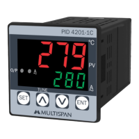
The Multispan PID 4201-1C is a PID controller designed for precise temperature and current control, featuring a compact design and user-friendly interface.

Function Description

The PID 4201-1C operates as a PID (Proportional-Integral-Derivative) or ON-OFF controller, selectable by the user. It is capable of measuring and controlling temperature using various sensor types (J, K, PT, PT.1) and current up to 30.0 A via a Current Transformer (CT). The device provides a clear digital display for both process value and setpoint, along with an output for control action. Key functionalities include:

  • Temperature Control: Supports a wide range of temperatures depending on the sensor type: 0 to 600°C for J type, 0 to 1200°C for K type, -99 to 400°C for PT type, and -99.9 to 400.0 for PT.1 type.
  • Current Measurement: Measures current from 0.0 to 30.0 A using a 1 CT.
  • Auto-Tuning: Features a PID auto-tuning function to automatically optimize control parameters for stable and accurate performance.
  • Set Point Setting: Allows users to easily set and adjust the desired process value.
  • Control Parameters: Provides access to various control parameters such as Proportional Band (PB), Integral Time (IT), Derivative Time (DT), Cycle Time (CT), and Offset (MR) for fine-tuning the control action.
  • Heater Break Indicator: Includes a heater break indicator (HbI) to alert users of potential issues with the heating element.
  • High/Low Set Limits: Allows setting of high (SHL) and low (SLL) limits for the process value.
  • Offset Correction: Offers an offset correction feature for sensor calibration.
  • Password Protection: Incorporates password protection for accessing configuration and control parameter settings, preventing unauthorized changes.
  • Error Indication: Displays specific error messages for sensor connection issues (e.g., "5-E" for reverse connection, "OPEn" for no connection).

Important Technical Specifications

  • Model: PID-4201-1C
  • Display:
    • Upper: 4-digit, 0.56" Red LED Display (for Process Value)
    • Lower: 4-digit, 0.33" Green LED Display (for Set Point/Current)
  • Size (mm): 48 (H) x 48 (W) x 95 (D) mm
  • Panel Cutout: 45 x 45 mm
  • Input: J, K, PT, PT.1 (for temperature); 1 CT (for ampere)
  • Range:
    • Temperature: J type: 0 to 600°C; K type: 0 to 1200°C; PT type: -99 to 400°C; PT.1: -99.9 to 400.0
    • Ampere: 0.0 to 30.0 A (1 CT)
  • Control Action: PID / ON-OFF (selectable)
  • Output:
    • 1 relay parallel SSR, 230V AC, 5A
    • SSR, 12V DC, 30mA
  • Power Supply: 100 to 250V AC, 50/60 Hz, Approx 3VA
  • Protection Level: IP-65 (Front side) as per IS/IEC 60529: 2001
  • Operating Temperature: 0°C to 55°C
  • Relative Humidity: Up to 95% RH Non Condensing

Usage Features

  • Key Operation:
    • SET key: Used to enter parameter settings, save changes, and in combination with other keys, access advanced functions.
    • UP/DOWN keys: Used to change values or select options.
    • SET + UP keys (6 seconds): Initiates/stops PID auto-tuning.
    • SET + DOWN keys (3 seconds): Accesses factory setting mode.
  • Basic Configuration: Accessible by entering password "73" to set input type (InPE), relay mode (rnod), PID/ON-OFF action (Pid), hysteresis (HYS), heater break indicator (HbI), set low limit (SLL), set high limit (SHL), and offset (OFSE).
  • Control Parameter Setting: Accessible by entering password "37" to adjust PID parameters such as Proportional Band (PB), Integral Time (IT), Derivative Time (DT), and Cycle Time (CT).
  • Factory Setting: Allows users to apply default factory values or escape from the setting.
  • Heater On/Off Control: Provides a dedicated setting to turn the heater on or off.
  • Power-On Display Sequence: Upon power-on, the device performs a self-test by turning on all digit segments for 1 second, then displays the previous or default sensor input and control action for 2 seconds, followed by the process value and current.
  • Sensor Error Indication: Clearly displays "5-E" for reverse sensor connection and "OPEn" for an open sensor circuit, aiding in quick troubleshooting.
  • Scrolling Display: While pressing the SET key for 5 seconds, the lower display scrolls through the set temperature and actual current, providing a quick overview of key operational values.

Maintenance Features

  • Cleaning: The equipment should be cleaned regularly to prevent blockage of ventilating parts. Use a clean, soft cloth; avoid isopropyl alcohol or other cleaning agents.
  • Ventilation: Ensure the equipment is kept clean to maintain proper ventilation.
  • Fuse: The fusible resistor must not be replaced by the operator.
  • Installation Guidelines:
    • Wiring: Ensure power supply is OFF during wiring. Use wires with adequate rating and twists for electromagnetic interference reduction. Power supply cables should have a cross-section of 1mm² or greater with 1.5kV insulation capacity.
    • Sensor Wiring: Use thermocouple compensation wires for thermocouple leads and low-resistance wiring (max 50Ω per line) for RTD types, ensuring no resistance differentials among the three wires.
    • Noise Reduction: Use standard power supply cables for better anti-noise effect.
    • Panel Mounting: Prepare a 45x45mm panel cutout. Fit the unit into the panel using the provided clamp.
    • Environment: Install the equipment away from heating sources, caustic vapors, oils, steam, or other unwanted process by-products.
    • Terminal Connections: Use specified crimp terminals (M3.5 screws) and tighten to a torque of 1.2 N.m. Do not connect anything to unused terminals.
  • Circuit Breaker/Mains Switch: A circuit breaker or mains switch must be installed between the power source and the supply terminal for easy ON/OFF function, placed in an accessible location.
  • Operating Environment: Use and store the instrument within the specified ambient temperature (0°C to 55°C) and humidity (up to 95% RH Non Condensing) ranges.

MULTISPAN PID 4201-1C Specifications

General IconGeneral
BrandMULTISPAN
ModelPID 4201-1C
CategoryController
LanguageEnglish

Related product manuals