LCD
SPEECH
LED ALERT
EEPROM
RECEIVER
BATTERY
ANTENNA
AUDIO
AND AGC
µP/GATE
ARRAY
(DECODER)
AUDIBLE
ALERT
VIBRATE
ALERT
R15
R22
R94
R93
R61
R9
R16
R1
MOTOR
PSG/10438/1
RPR 550IS Series
TM1188 Issue 1 Page 3 - 5
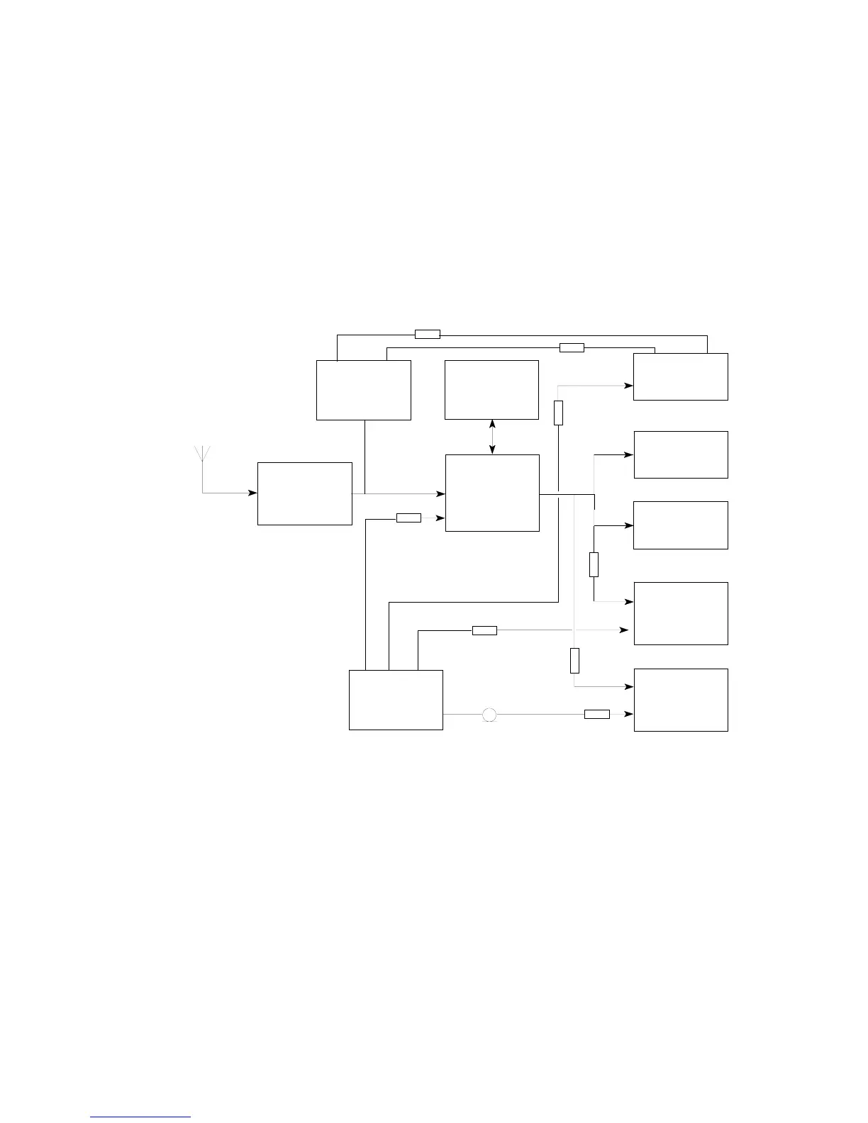
Figure 3: Overall Block Diagram
FUNCTIONAL DESCRIPTION
7. Figure 3 shows the block diagram of the functional areas of the RPR 550IS Series.
Full circuit diagrams for the radio and main board of each type of pager appear in
Section 7.
Signal Processing
8. The RF signal is detected by the antenna and fed to a single conversion
superheterodyne receiver where the RF is converted into IF and subsequently
demodulated into audio and data. The data is fed to the decoder circuit where the
memory, alert lamp, LCD, audible alert and vibrate alert (if fitted) are activated.