8
3.2.3 Hot Weather Protection
o Stage operation:
• If the house temperature rises to Thermostat 3’s set temperature, the RBU-27 SE launches Cooling
Stage 1 and operates Fans 1-2 and 3-4 to lower temperatures.
• If temperature continues to rise to Thermostat 4’s set temperature, the RBU-27 SE launches Cooling Stage
2 (Fans 5-6, 7-8, and 9-10) and uses the Inlet or Tunnel option as well.
• If the temperature continues to rise to Thermostat’s 5 set temperature, Cooling Stage 3 (Fans 11-12, 13-14,
and 15-16) launches.
• If Thermostat 4’s set temperature is lower than Thermostat 3’s set temperature, Cooling Stage 1 begins
simultaneously with Cooling Stage 2.
o Inlet or Tunnel option: The inlets/tunnels open when the first cooling stage begins. In practice, this means
the inlets/tunnels open when Cooling Stage 1 begins.
• If Thermostats 3 and 4's set temperature are higher than Thermostat 5's, the inlet/tunnel opens when
Cooling Stage 3 begins.
• If Thermostats 3's set temperature is higher than Thermostat 4 and 5's, the inlet/tunnel opens when
Cooling Stage 2 begins.
Table 2 lists the cooling stages activation and timer delays.
Table 2: Cooling Device Settings
1 3 Fans 1-4 and Inlet or Tunnel Curtains 60 seconds
Fans 1-4 / 5-10 and Inlet or Tunnel Curtains
Fans 1-10 / 12-16 and Inlet or Tunnel Curtains
N/A Fail safe delay 30 seconds
NOTE: Rotem recommends using the default timer delays; however the timer can be adjusted to any time setting on
the potentiometer.
NOTE: Timer delay differs if when the unit is in Fail Safe mode. Refer to Platinum Fail Safe.
To adjust the delay:
1. Disconnect power from the RBU-27 SE.
2. Open the unit.
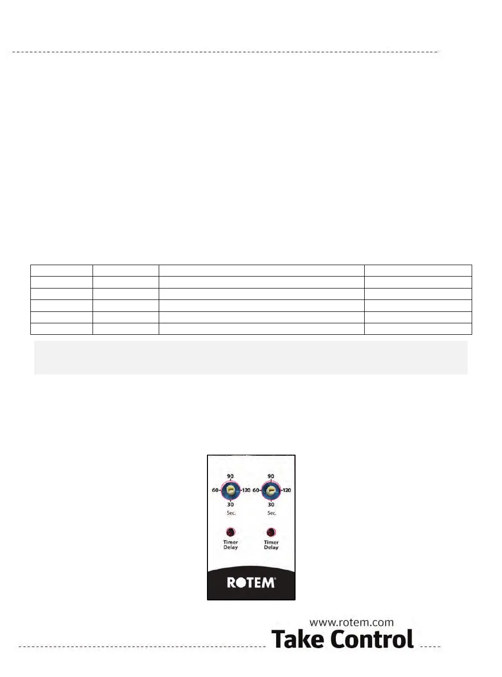
3. Adjust the timer delay potentiometers as required (Figure 3).
4. Figure 4 illustrates which potentiometer controls the delay for the different stages.
Figure 3: Timer Delay Unit
 Loading...