12
o Figure 8: Heater Wiring
o Figure 9: Fail Safe Wiring
o Figure 10: Relays Diagram – Inlet / Tunnel – Section 3
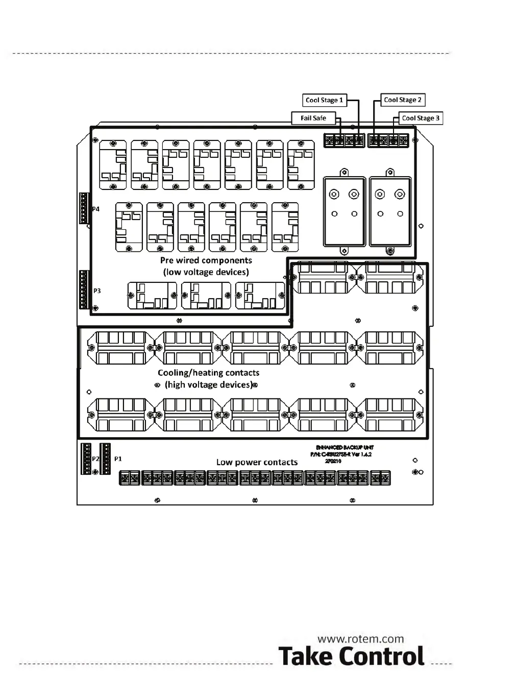
Figure 4: Card View
Figure 4 presents a view of the card divided into the following main sub-units:
o Section 1 - Pre-wired sub-units: Designed to be used only in case an error occurs. Only authorized
technicians can replace or repair these subunits.
o Section 2 - Fans and heater contacts: Designed to define the relays that active the cool pad, fans, and the
heaters. Figure 6, Figure 7, and Figure 8 focus on defining the connections to the controller and other
equipment.
o Section 3 - Thermostat and vents connection sub-unit: Illustrated in Figure 10. Designed to connect the
Tunnel curtain and the Inlet.
Note that each cool pad, fan, and heater has a separate pair of relay contacts capable of directly driving the load. The
board connections are written on the board in the following order (left to right):
 Loading...