© Munters AB, 2020 28
3.4.6.5 Ammonia Sensor Wiring
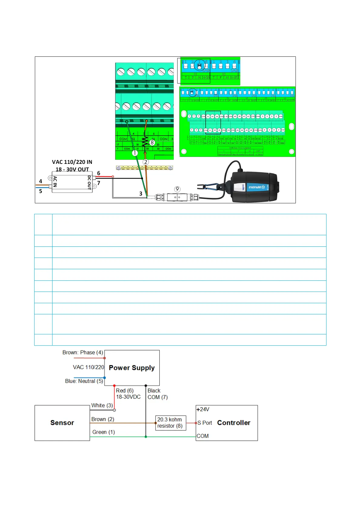
Figure 22: Ammonia Sensor Wiring
1 COM port (Green wire)
2 S port (Brown wire)
3 White wire
4 Phase (Brown wire)
5 Neutral (Blue wire)
6 18-30VDC (Red wire)
7 COM (Black wire)
8
20.3 kohm resistor (Note: The resistor comes supplied with the sensor but must be installed on-
site)
9 Quick connector
Figure 23: Ammonia Wiring Schematic
•
Connect an ammonia sensor to a:
o
S port. In the corresponding dipswitch, raise dipswitch 3 (analog input).