Murata Electronics Corporation 15 6/2/2021
4. MODEM INTERFACE
Electrical connection to the WIT2420 is made through a 16-pin male header on the modem
module. The signals are 3.3 volt signals and form an RS-232 style asynchronous serial
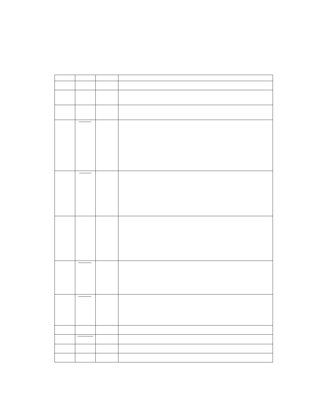
interface. The table below provides the connector pinout.
Signal and chassis ground
Transmit data. Input for serial data to be transmitted. In Control
Mode also used to transmit modem commands to the modem.
Receive data. Output for received serial data. In Control Mode,
also carries receive modem status from the modem.
Configuration selector. Used to switch between Control and Data
Modes. Normally, CFG will be set for Data Mode. An internal 10K
pull-up enables Data Mode if this signal is left unconnected.
Control Mode is also accessible by transmitting an escape
sequence immediately after wake up or power up.
(0v) 1 = Control Mode
(3.3v) 0 = Data Mode
Request to send. Gates the flow of receive data from the radio to
the user on or off. In normal operation this signal should be
asserted. When negated, the WIT2420 buffers receive data until
RTS is asserted.
(0v) 1 = Receive data (RxD) enabled
(3.3v) 0 = Receive data (RxD) disabled.
Sleeps/wakes radio transceiver. In sleep mode all radio functions
are disabled consuming less than 50µA. At wake up, any user
programmed configuration settings are refreshed from non-volatile
memory, clearing any temporary settings that may have been set.
(3.3v) 1 = Sleep Radio
(0v) 0 = Wake Radio
Data carrier detect. For remotes, indicates the remote has
successfully acquired the hopping pattern of the base station.
(0v) 1 = Carrier detected (synchronized)
(3.3v) 0 = No carrier detected (not synchronized)
Clear to send. Used to control transmit flow from the user to the
radio.
(0v) 1 = Transmit buffer not full, continue transmitting
(3.3v) 0 = Transmit buffer full, stop transmitting
Reserved for future use. Do not connect.
Reserved for future use. Do not connect.
Positive supply. Min 3.3 v, 5.0 v nominal, 10.0 v max.