Murata Electronics Corporation 17 6/2/2021
asynchronous into the radio serial port). If the base transmits continuously at a higher rate
than this, unless the default settings are changed, the transmit buffer will eventually
overflow. To allow a higher base throughput, either increase the base slot size or the hop
duration or both. A similar analysis needs to be performed for the remote radios. Refer to
Section 2.2.3 TDMA Mode for the remote throughput calculation.
4.4 Power-On Reset Requirements
The WIT2420 has an internal reset circuit that provides 100ms for power to the module to be
applied and stabilized as well as removed. If the host cannot guarantee that power will be
within the specified voltage range within 100ms of power being applied and be completely
removed within 100ms of dropping below 3.3 volts, the host must apply a Reset signal to the
module on pin 10 of the power/data connector. The operation of the microprocessor in the
WIT2420 is undefined for voltages below 2.7 volts. If such supply voltages are present for
more than 100ms, non-volatile configuration and program parameters can be overwritten and
corrupted. This is particularly important in battery operated systems where a low battery
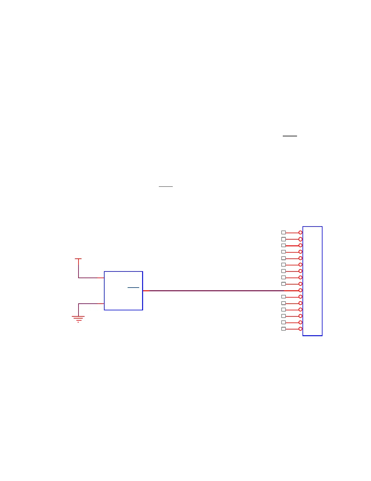
condition may present a “brown out” voltage for an indefinite period of time. The circuit
schematic below will provide a Reset signal to the module whenever the supply voltage falls
below 2.98 volts. Note that the radio is not specified to operate below 3.3 volts.