Murata Electronics Corporation 16 6/2/2021
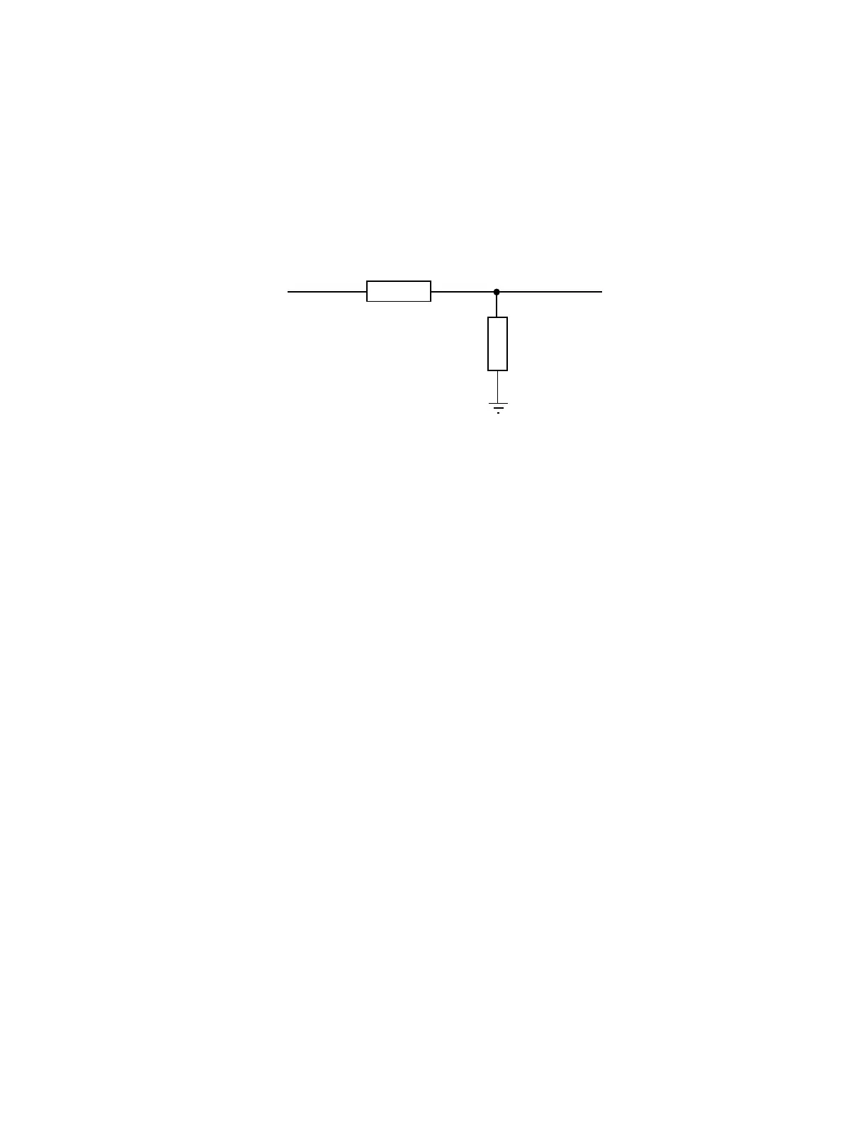
4.1. Interfacing to 5 Volt Systems
The modem interface signals on the WIT2420 are 3.3 volt signals. To interface to 5 volt
signals, the resistor divider network shown below must be placed between the 5 volt signal
outputs and the WIT2420 signal inputs. The output voltage swing of the WIT2420 3.3 volt
signals is sufficient to drive 5 volt logic inputs.
4.2 Evaluation Unit and OEM Module Differences
The evaluation unit has an RS-232 transceiver that translates RS-232 level signals to 3.3 volt
signals for input into the OEM module inside the evaluation unit. A typical schematic is
shown in Appendix 7.5. The OEM module does not have any type of RS-232 transceiver and
cannot handle the RS-232 voltages. This allows the OEM module to be easily integrated into
any 3.3 volt system without any logic signal translation. In order for the OEM module to
function properly several pins need to be driven low or tied to ground. Pin 5 (RTS) and pin 6
(SLEEP) need to be pulled to ground on the 16-pin male header. If you have the OEM
module interfaced to an RS-232 transceiver, RTS and DTR need to be pulled high on the
transceiver side. In the evaluation unit, RTS and DTR are pulled high on the transceiver side
so the evaluation unit will work with these signals not connected.
4.3 Three Wire Operation
The WIT2420 can be operated in a three wire configuration using just TxD, RxD and
Ground. To operate the WIT2420 in this configuration, the Sleep and RTS signals must be
tied to ground. These signals are pulled up on the WIT2420 module and if left disconnected
will put the radio into sleep mode and RTS will be deasserted.
The WIT2420 does not support software flow control (XON/XOFF). Thus when using a
three wire configuration, there is no flow control. The radio configuration and/or the
application must insure the transmit and receive buffers do not overflow. The WIT2420 has a
2048-byte transmit buffer and a 1024-byte receive buffer. For example, the default settings
for the base slot size and hop duration are 08H and 90H respectively. The 08H base slot size
allows the base to send 32 bytes of data per hop. The 90H hop duration provides a 10ms hop
dwell time. These default settings provide a base throughput of 40kbps (Since the over the air
transmission is synchronous, the 32kbps synchronous over the air rate is equivalent to 40kbps