Sections 40 & 75 00-02-0594
04-16-10 - 3 -
Setting Up the Cascade
To enter the SETUP MODE, first remove DC power to the Cascade controller for approximately 10
seconds.
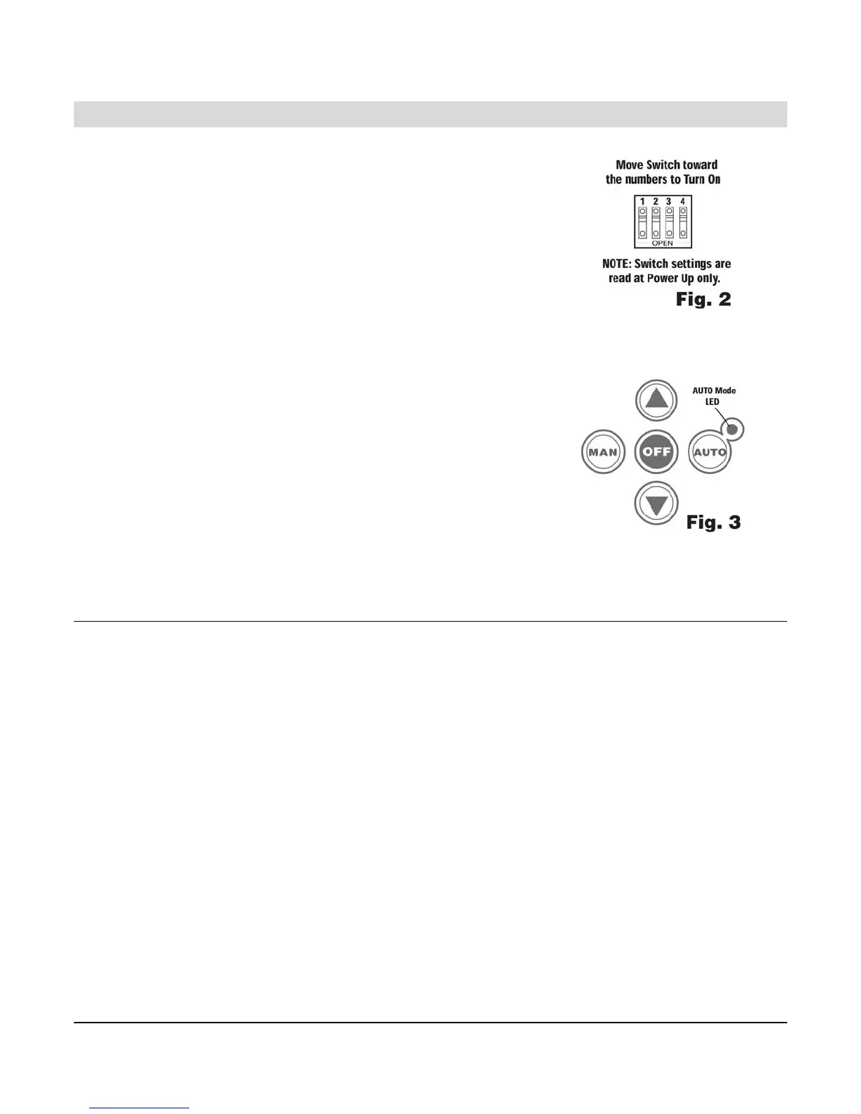
On the back of the controller are four DIP switches, set switch #1 to ON (see
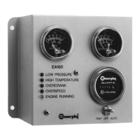
schematic at right) then restore DC power. The AUTO mode LED will
blink to indicate that the Cascade is in the SETUP MODE.
When in the SETUP MODE, pressing the “MAN” (Manual) button steps up
thru the entire list of parameters. The pattern of the top six LEDs, LEDs
Bank 1 (see “Fig. 1”), is used to indicate which parameter is selected.
The pattern will change once each time the “MAN” button is pressed.
Pressing the “OFF” button steps up thru all the available values for each
parameter. The pattern of the bottom five LEDs, LEDs Bank 2 (see “Fig. 1”), is used to indicate
which value is selected. The pattern will change once each time the OFF button is pushed.
Pressing the “AUTO” button stores the displayed value.
If any value is changed, it will blink until stored, except a value of zero. If
any value is changed but not stored, and then the parameter is
changed, the value will still be what was shown originally.
If you accidentally go past a desired parameter or value, you can step
back by pressing the down arrow button.
The parameter/value list and corresponding LED indication are shown on
Table 1 – Parameter Values and Corresponding LED Indication.
When you are finished with setup, set switch #1 to in the Normal
Operating Position (OPEN), remove DC power for 10 seconds, then restore DC power.
Modes of Operation
Setup Mode
Refer to the section “Setting Up the Cascade” and “Table 1 – Parameter Values and Corresponding LED
Indication”.
Normal Operating Mode (Engine Control Mode)
The DIP switch #1 must be in the open position in order to enter this mode upon power up. “Table 2 – LED
States for Normal Operating Mode” shows the meaning of each LED state for this mode.
Error Mode
Upon power up, when the DIP switch #1 is in the normal operating position (open position) and an error is
detected in the user configuration, the Error Mode will be accessed. The LEDs will blink fast indicating the error.
To correct the errors before the unit can operate in Engine Control Mode, the user will need to go back to Setup
Mode. “Table 3 – Error Codes LED States” and “Table 4 – Configuration Error Codes” show the meaning of each
LED state and configuration for the Error Mode.
Sleep Mode
In Auto Mode the Cascade will enter Sleep Mode after 2 minutes of inactivity. The unit will exit Sleep Mode on
key press or remote call to run. It will not enter Sleep Mode if there is an active fault.