Do you have a question about the Murphy EMS PRO and is the answer not in the manual?
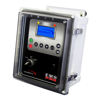
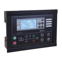
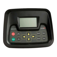
Describes the EMS PRO controller's features and capabilities.
Details the function of each button on the controller's keypad.
Explains the operation of the 3-position key switch (AUTO, OFF, MAN).
Lists and describes the various information screens shown on the controller.
Guides the user through setting the real-time clock and date.
Provides steps to configure the controller for mechanical engines.
Describes start/stop using a single remote contact.
Explains start/stop logic using two float contacts.
Details start/stop via momentary contacts.
Covers start/stop using transducer set points.
Explains start/stop using panel-mounted buttons.
Describes throttling the engine to a maximum RPM set point.
Explains throttling controlled by transducer set points.
Details throttling using an external potentiometer.
Describes start/stop and throttling based on pressure.
Covers start/stop and throttling based on level.
Details start/stop based on temperature.
Explains how to initiate Diesel Particulate Filter regeneration.
Guides the user to switch between metric and English units.
Describes the automatic engine start and stop procedures.
Details the steps involved in the auto start sequence.
Explains the process for the auto stop sequence.
Describes the manual start procedure.
Details the manual stop procedure.
Explains how the controller stores and displays shutdown events.
Describes the feature for backup operation using float switches.
Explains timed engine starts based on the clock.
Details the shutdown mechanism for overspeed conditions.
Explains how auxiliary inputs and outputs are configured.
Describes the controller's standby mode and its activation.
Lists and describes the S-Numbers for system customization.
Lists and describes the P-Numbers for clock functions and history.
Lists and describes the controller's digital input signals.
Lists and describes the controller's analog input signals.
Lists and describes the controller's digital output signals.
Explains the function of shunts on the PCBA.
Guides on adjusting the display contrast.
Provides essential wiring guidelines for reliable installation.
Details the CAN port for J1939 communications.
Describes the RS-485 port for gages or Modbus.
Explains the RS-232 port for Modbus and program upload.
Describes the Modbus RTU communication protocol.
Lists accessible registers and their meanings.
Provides the access code for P-numbers.
Provides the access code for S-numbers.
Details mounting instructions and physical dimensions.
Lists electrical and environmental operating limits.
Describes the enclosure type and environmental sealing.
Briefly lists the types and quantities of I/O.
Details the interface and communication ports.
| Brand | Murphy |
|---|---|
| Model | EMS PRO |
| Category | Controller |
| Language | English |