Section 40 00-02-0716
2013-06-03 - 35 -
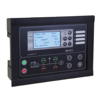
CPU PCB WIRING INTERFACE LIST (JP5) MOLEX 4 PIN CONNECTOR
Assignment
Assignment
RS-232
RS-232 port designated for Modbus RTU (slave to a master) for SCADA, and to upload the actual
operating program.
NOTE: Modification to controller enclosure is required to use these ports.
CPU PCB WIRING INTERFACE LIST (J2) DB9 CONNECTOR
Program Function Assignment
Description
The EMS PRO implements a MODBUS RTU style communications protocol. The following will
describe the communications and the register and coil implementation for the EMS PRO.
Protocol
The EMS PRO controller will reply to RTU MODBUS communications. This communications protocol
uses RS232 standards set to 9600 baud rate, no parity, eight (8) bits and one (1) stop bit.
• MODBUS® command code 03
Read Holding Register Status: Reads the binary contents of the holding register in the EMS
PRO controller.
• MODBUS® command code 06
Preset Single Register: Presets a value into a single holding register.
• MODBUS® command code 16
Preset Multiple Registers: Presets values in a sequence of holding registers.