Operation
21
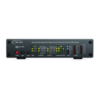
»EXTERN« – Selecting external Clock References
External clock references can be selected when the MC-3+USB is set to »EXTERN« in the »MODE« menu.
The above example shows the MC-3+USB locked to an external Word Clock signal. Its clock rate of 48.0 kHz is displayed in the
»CLOCK
IN« section on the right hand side of the front panel. You can choose the other available inputs by repeatedly pressing
the »SELECT« key. The example furthermore shows that different multiplication factors have been selected in the »CLOCK MUL-
TIPLIERS« menu that provide the following outputs:
Word Clock output pair (1): reference clock x 1 = 48.0 kHz output clock rate
ord Clock output pair (2): reference clock x 8 = 384.0 kHz output clock rate
S/P-DIF output (3): reference clock x 2 = 96.0 kHz output clock rate
AES3/11 & AES3id outputs (4): reference clock x 1 = 48.0 kHz output clock rate
Selecting »10.0M« as clock reference
Upon selecting the »10.0M« clock reference option, the »44.1 kHz« LED in the »CLOCK OUT« menu will light up. You can
choose one of the seven available clock rates that the internal ultra-low jitter clock generator provides by pressing the
»SELECT« key. The outgoing clock signals are now set to the chosen base clock rate, but are locked to the frequency of the
externally applied 10.0 MHz reference signal. Clock multipliers for the clock outputs can still be selected freely, as described in
the »Selecting clock multipliers« section further below.
Selecting »USB-PCM and »USB-DSD/DoP« as clock reference
When selecting »USB-PCM« and »USB-DSD/DoP« as clock reference, the embedded clock rate of the USB audio stream will be
extracted and will be used as the base clock rate. Clock multipliers for the clock outputs can still be selected freely. The »CLOCK
IN« section indicates the extracted base clock rate. The USB audio stream will not be converted to the digital audio outputs
in this mode of operation! Instead, the audio outputs will transmit empty audio frame signals (AES3-/S/P-DIF clock signals
without audio content).
Selecting »AES3/11«, »S/P-DIF
OP«, »S/P-DIF BNC« as Clock Reference
When selecting one of these three clock reference options, the sampling rate embedded in the digital audio signal will be ex-
tracted and will be used as the base clock rate. Clock multipliers for the clock outputs can still be selected freely. The »CLOCK
IN« section indicates the extracted base clock rate. No format conversion of AES3 or S/P-DIF signals to the digital audio outputs
will take place in this mode. Instead, the audio outputs will transmit empty audio frame signals (AES3- /S/P-DIF clock signals
without audio content).
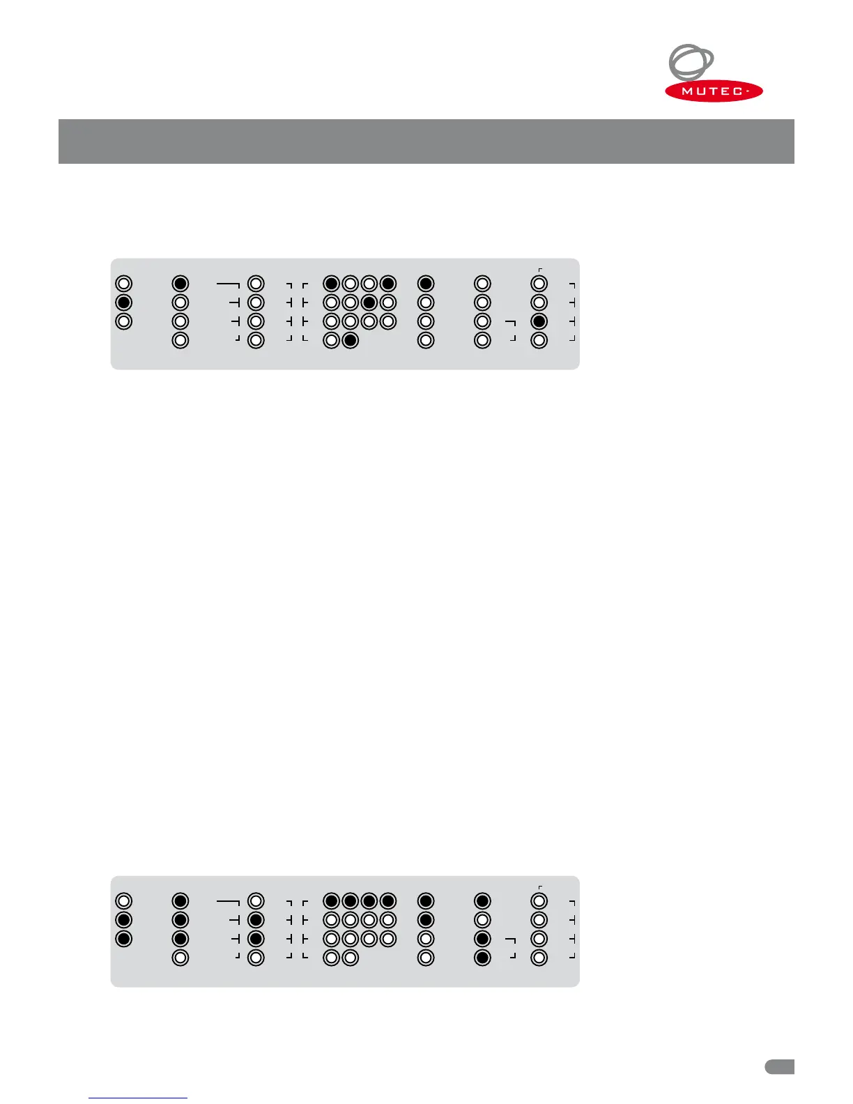
»RE-CLK« – Selecting Audio Re-Clocking
The MC-3+USB is capable of receiving PCM or DSD/DoP streams via USB, as well as digital audio signals in the AES3 and S/P-
DIF formats (all selectable in the »REFERENCE« menu), and significantly improving their sound quality by re-clocking (RE-CLK).
The example above shows the MC-3+USB set to the externally referenced re-clocking mode. A DSD256 signal is being received
via USB (refer to »REFERENCE« & »CLOCK
IN«). The audio outputs are set to a sampling rate of 176.4 kHz (refer to »CLOCK
CLOCK MULTIPLIERS
1 2 3 4
MODE
32.0
48.0
INTERN
RE
-
CLK
EXTERN
×
1
×
8
×
4
×
244.1
88.2
96.0
×
256 SC
×
512
×
256
WC176.4
192.0
REFERENCE CLOCK OUT
WCLK
1
–
10.0M
USB
-
PCM
AES3/11
S/P
-
DIF BNC
AES3/11id
S/P
-
DIF OP
USB
-
DSD/DoP
STATUS
LOCK
MAIN REF
LOCK
RE
-
CLK REF
CLOCK IN
32.0
48.0
DoP
AUDIO
HOLD
44.1
DSD
88.2
64
128
96.0
176.4
192.0256
1
–
10.0M