26
Appendix
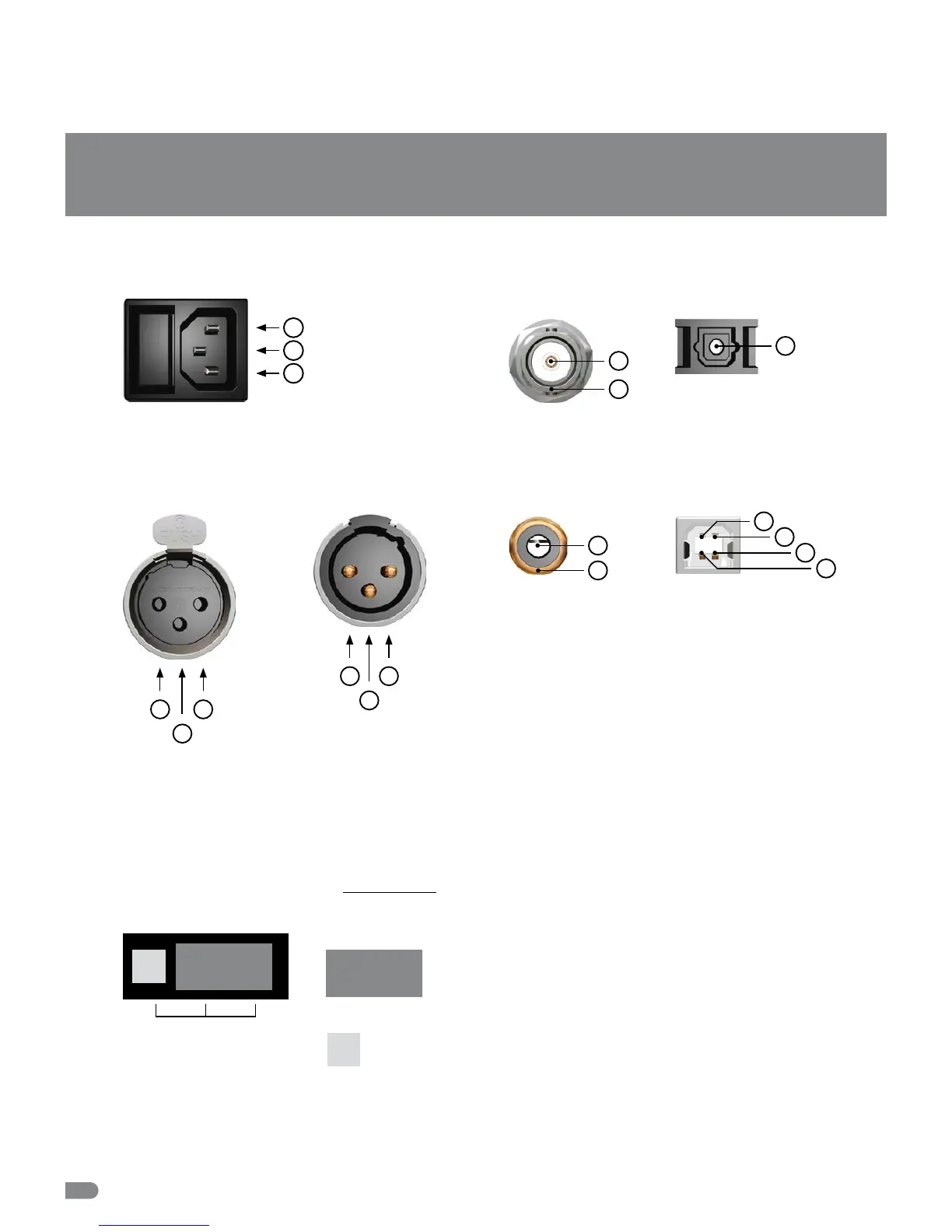
Pin Assignment of the Connectors
Mains
1
1 Live, phase (brown; USA: black)
2 Protective earth (green/yellow; USA: green)
3 Neutral (blue; USA: white)
2
3
USB Input and
Output
1 D
–
2 VBUS,
+
5 V
3 GND
4 D
+
Switching off the Termination of the Word Clock and 1–10.0 MHz Input
Attention
Disconnect the unit from the mains before opening! Remount the aluminium cover thoroughly before you attempt
to operate the unit!
When the MC-3+USB is shipped, the BNC-based Word Clock input
connector is terminated internally with 75 Ω. Therefore, one jumper is
put on two pins - Position 2 - of the 3-pin socket JP1.
(see adjacent sketch on page 25).
2
1
3
4
Optical TOSLINK Input/Output
for S/P-DIF
1
1 Optical signal
BNC Input/Output for
Word Clock, 10.0 MHz
1 Signal
2 Ground
1
2
2
3
1
1 Audio ground
2 Conductor (hot / +)
3 Conductor (cold)
AES/EBU, XLR, Input
for AES3/11
RCA, Input/Output
for S/P-DIF
1 Audio signal
2 Audio ground
1
2
1
3
2
1 Ground
2 Conductor (hot / +)
3 Conductor (cold)
AES/EBU, XLR, Output
for AES3/11
NOTE:
The RCA-based S/P-DIF
inputs and outputs are
not galvanically isolated,
due to IEC 60958.
JP1
Jumper:
1 2
Free Pin:
Jumper Position 2
=
Termination