Chapter 7 Related Documents
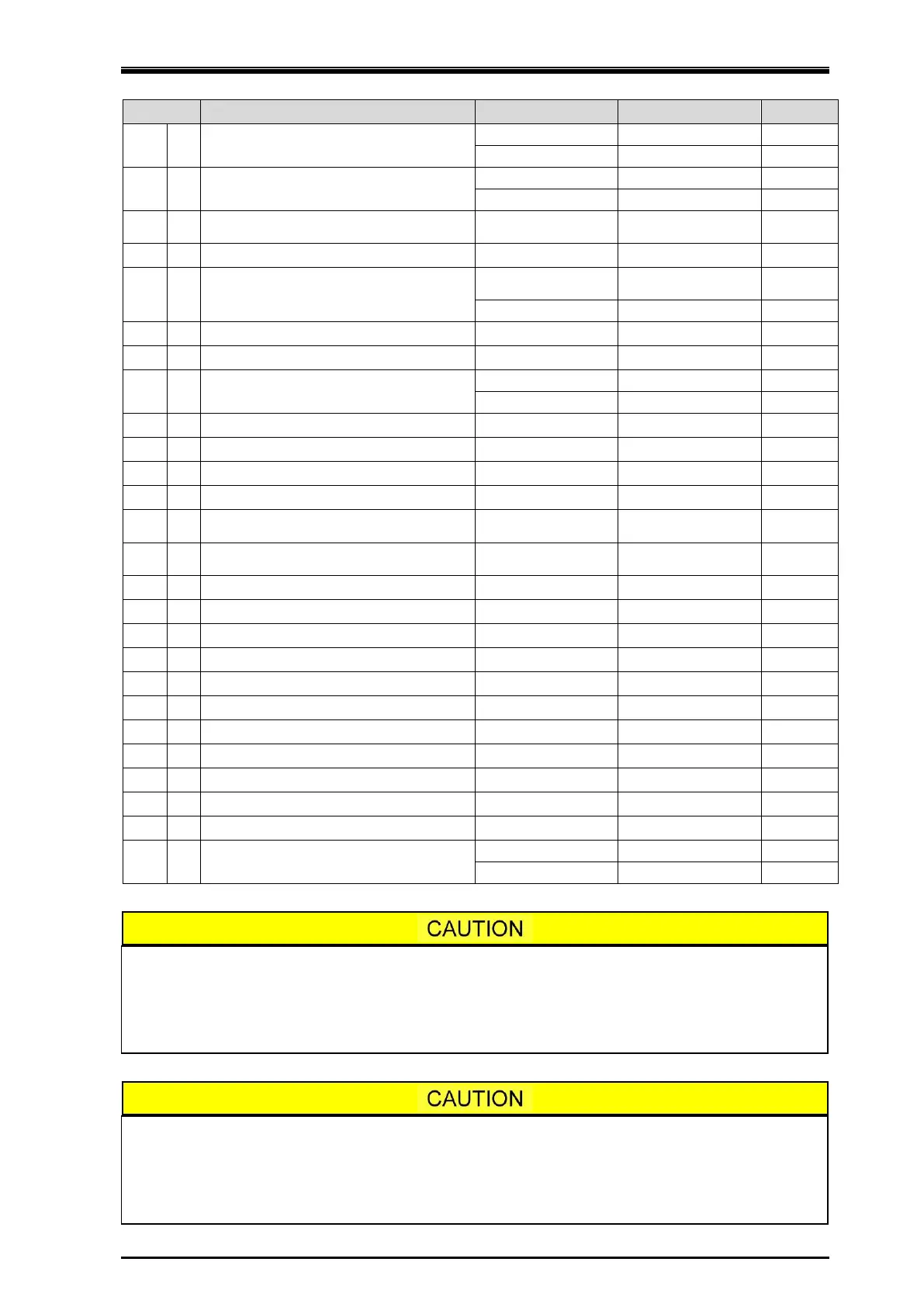
UD-series Screw Compressor 7.2 Parts Configuration Table 400*UD
7-32
217 2 Stud Bolt & Nut
217 3 Stud Bolt & Nut
218
Flange, Injection Oil Supply
219
Gasket, Injection Oil Supply
220
Stud Bolt & Nut
221
Flange, Injection Oil Supply
222
Gasket, Injection Oil Supply
223
Stud Bolt & Nut
237
246
247
Hexagon Socket Head Cap Screw
249
250
Gasket, Loading oil connection for
hydraulic cylinder
267
Spring Washer, Hexagon Socket Head
Cap Screw
325
326
346
432
433
597
605
664
674
999
999
999
3
Stud Bolt & Nut
The part code of the O-ring is the one assigned to NBR which is standard material.
When the material of the O-ring is other than NBR, a different part code is used for
each material.
If you are using O-rings made from other than the standard material, please contact
MAYEKAWA when placing an order.
The Code No. of parts shown in parentheses below is applied to the product until the
end of November, 2014:
(P/N 120 Unloader Indicator Assembly, P/N 125 Micro-Switch, P/N 129 Potentiometer)
For the Code No. of new type indicator part, refer to the separately dedicated
Instruction manual for it.