2205Q2JE-HO-S6-N_2020.01.
Chapter 7 Related Documents
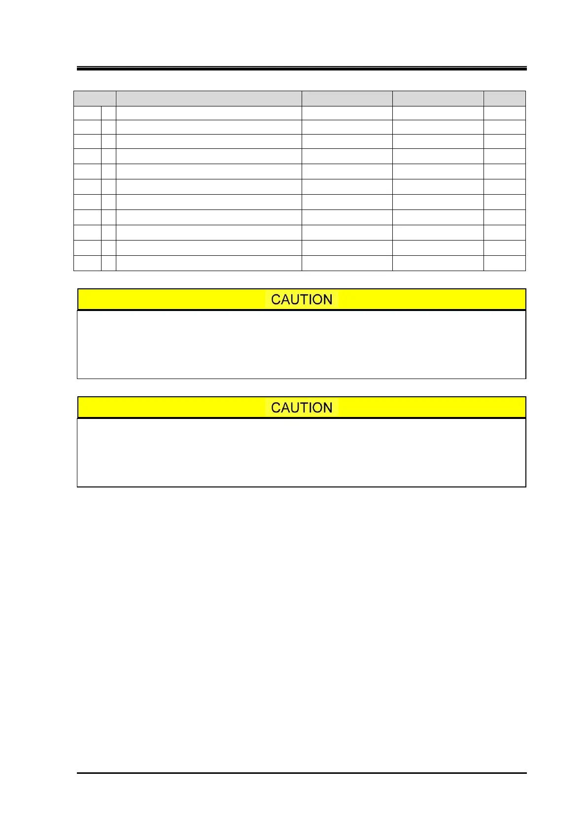
SCV-series Screw Compressor 7.2 Parts Configuration Table 320V*D
7-24
Hexagon Head Bolt
NF06-032 R1 1/4 1
NF06-004 R1/4 1
Conical Spring Washer, Vi Adjusting Rod
Conical Spring Washer, Vi Adjusting Rod
ND160-036 M36 1
Cover Plate, Liquid injection Flange
CS71500-025 MYK25A 1
The part code of the O-ring is the one assigned to NBR which is standard material.
When the material of the O-ring is other than NBR, a different part code is used for
each material.
If you are using O-rings made from other than the standard material, please contact
MAYEKAWA when placing an order.
The Code No. of parts shown in parentheses below is applied to the product until the
end of November, 2014:
(P/N 120 Unloader Indicator Assembly, P/N 125 Micro-Switch, P/N 129 Potentiometer)
For the Code No. of new type indicator part, refer to the separately dedicated
Instruction manual for it.