Chapter 3 Installation
UD-series Screw Compressor 3.2 Installation Works
3-3
3.2.4 Preparation for Installation
Installation Space
Secure sufficient working space for easy operation, cleaning, maintenance, and inspection.
Illumination
Prepare illumination devices which allow easy operation, cleaning, maintenance, and inspection.
Ventilation
If natural ventilation is insufficient, install ventilation fans according to the relevant regulations.
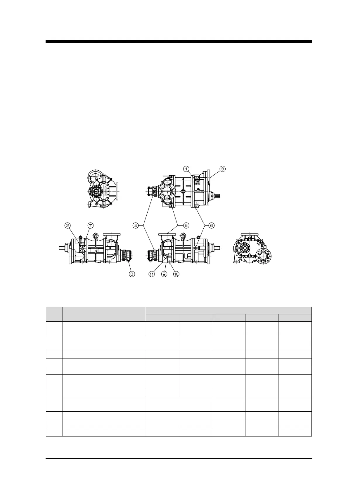
Connecting Port of Compressor
Figure 3-1 Connecting Port of Compressor
(125 – 320)
Table 3-1 Connecting Port of Compressor (125 – 320, Cast iron case)
Note 1:Cast iron casings from 160 to 320*UD were discontinued in 2010.
No. Item
Connecting port for liquid
injection1
MYK 10A MYK 20A MYK 25A MYK 32A MYK 50A
Connecting port for liquid
injection2
Rc 1/4 Rc 3/8 Rc 1/2 Rc 1/2 Rc 3/4
(
)
Lubricating oil main supply
port
(
)
Rc 3/8 Rc 1/2 MYK 20A MYK 25A MYK 40A
Economizer connecting port
Control wiring connector for
indicator
2-PF 3/4 2-PF 3/4 2-PF 3/4 2-PF 3/4 2-PF 3/4
(
)
Please check the figure for details.



 To Next Page