Chapter 5 Maintenance and Inspection
UD-series Screw Compressor 5.4 Disassembly and Inspection
5-30
Thrust Bearing Gland (2) Lock Nut (1)
(The photograph used is 400 VMD) VMD and MUD have different points.
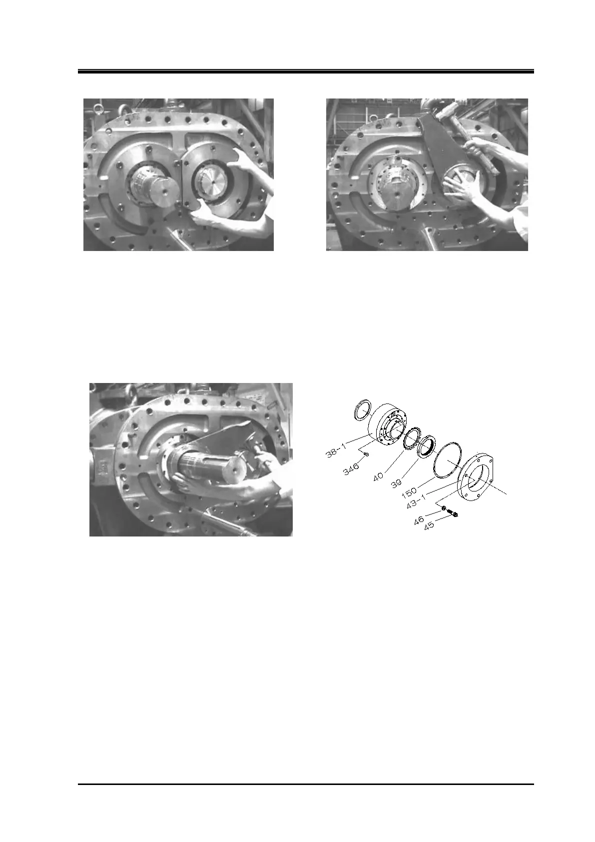
TPTB assembly
a) Use the lock nut wrench of the special disassembly tool to loosen the lock nut and remove the
lock nut and lock washer.
Lock nut (2) Figure 5-15 Development View of the Thrust Bearing
b)
Remove the key on the shaft and store it in a safe place.
c) Insert two eye bolts into the bolt holes on the tilting pad thrust bearings and pull out the tilting
pad thrust bearings until the bolt holes on the top of the bearings are visible axially.
d) Insert the lifting bolt into the hole on the tilting pad thrust bearing and lift it.
Pull out the tilting
pad thrust bearing from the bearing box.
 Loading...


