Chapter 5 Maintenance and Inspection
UD-series Screw Compressor 5.4 Disassembly and Inspection
5-29
Inspection
a) After thoroughly cleaning the thrust bearings, remove the cleaning solution with compressed
air.
First, make sure that the surface of the ball is evenly shiny and that there are no
scratches or flaking.
Next, inspect the corners of the retainer (thrust bearing retainer) ball hole for blisters and
wear.
In either case, replace the bearing set.
b) Hold one of the bearings in your hand and rotate the outer ring by hand with the inner ring
facing downward.
(Make sure the inside of the combination is facing down). If the rotation is
not smooth and it is uneven or hooked, it is caused by dust or scratchesIn that case, check
again and wash or replace the bearing set if necessary.
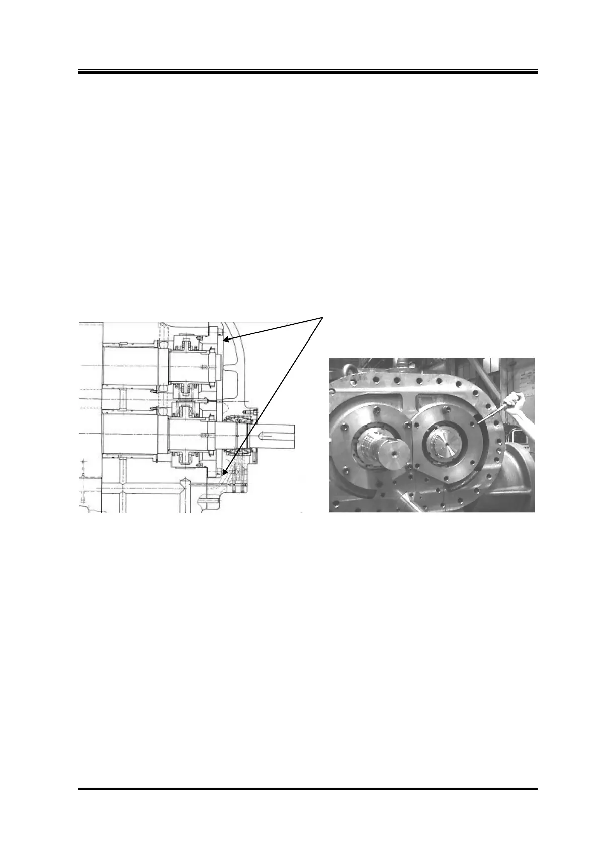
Tilting pad thrust bearing (TPTB, 400*UD)
Disassembly
Thrust Bearing Gland
Figure 5-14 TPTB Thrust Bearing Gland (1)
a)
Loosen the hexagon socket head cap screw and insert the lifting eye bolt into the bolt hole on
the upper part of the thrust bearing gland.
b)
Lift up the thrust bearing gland, remove the bolt, and insert the safety bolt on top of the thrust
bearing gland.
Pull out the thrust bearing gland using a flathead screwdriver. Remove the
thrust bearing gland and pull out the other thrust bearing gland in the same way.
 Loading...

