Chapter 5 Maintenance and Inspection
UD-series Screw Compressor 5.4 Disassembly and Inspection
5-28
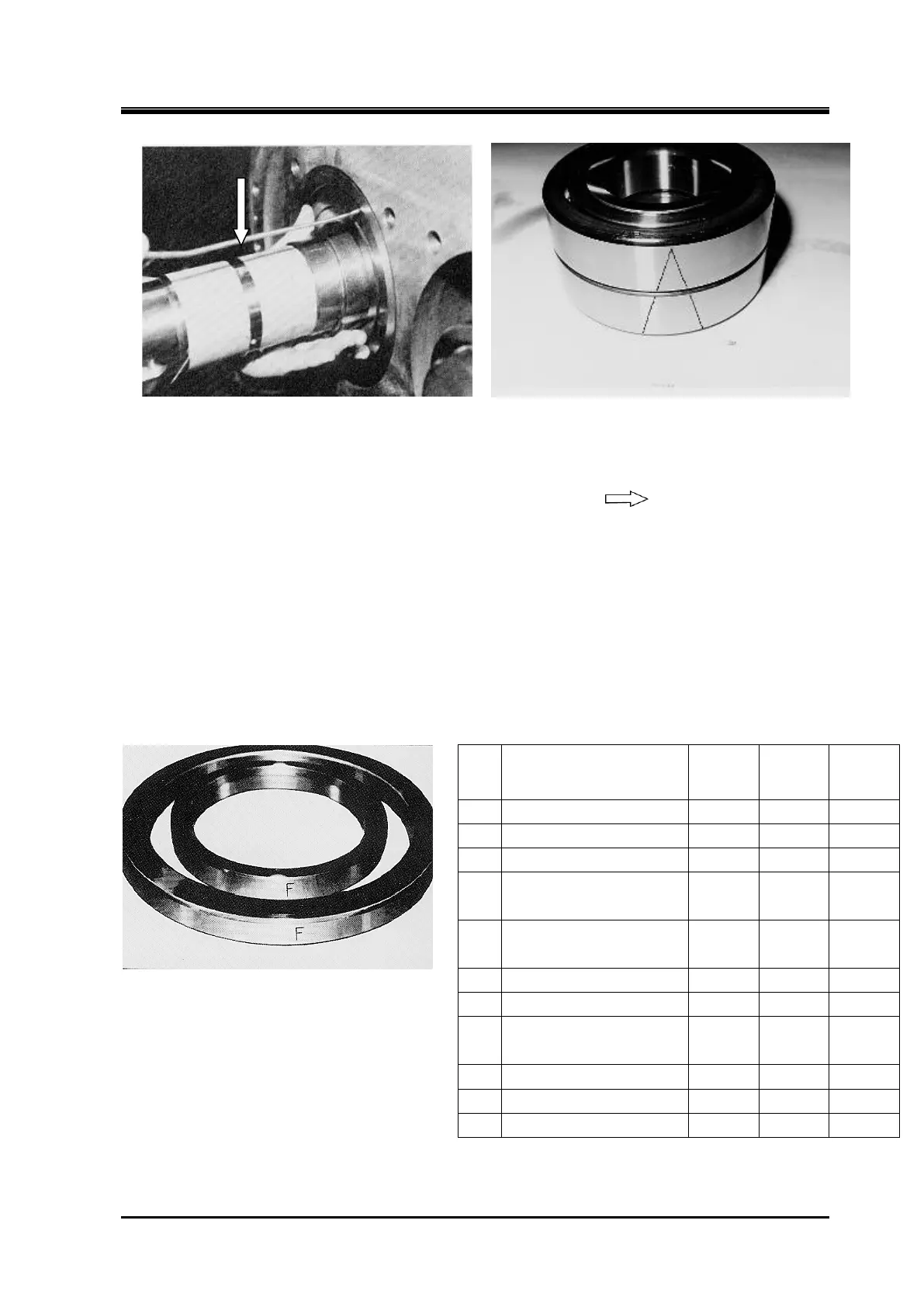
d) The thrust bearing inner ring and rotor shaft have a clearance fit. Prepare a slightly bent wire
tip with a diameter (φ) of 2 to 3mm flattened, insert it between the outer ring of the bearing
and the retainer, hook it, and pull it out toward you “see arrow
.
e) Remove the thrust adjustment washers “part number 42” and thrust bearing spacer “part
number 41” on the inside “some models do not have a spacer”.
Place the removed adjustment washer and spacer separately for the M rotor and F rotor
(There is a engrave indicating the rotor used. If the assembly position is mistaken during
reassembly, the end clearance between the discharge end surface and the bearing head end
surface will not be maintained correctly, resulting in performance degradation and seizure of
the end surface. )
Pulling out the Thrust bearing
Thrust bearing (1 set)
The Marking of Thrust bearing outer race
spacer and alignment spacer
№ Part name
125~
200
250 320
Outer Race
Alignment
Lock Washer
150
237
250
 Loading...

