Rev. 9-09-16 Part #C-00084
www.NabcoEntrances.com Magnum 4A Control Wiring and Adjustment Manual
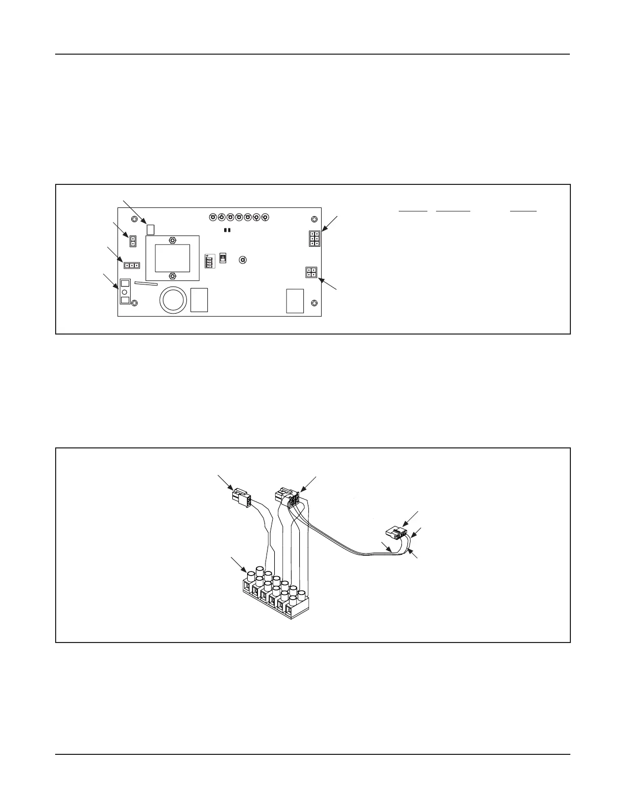
Magnum 4A Board Terminals 3-7
.
Figure 3-1
DN 0596
F1
J2
J4
J5
J1
Terminal Connector Harness
J1 Input Signal Main
J2 Auxiliary Power Main
J4 Incoming PowerPower
J5 Motor Motor
F1 Rese able Fuse
Non-Replaceable
N/A
F2 Not Rese ableFuse N/A
LED
TRANSFORMER
AUX
PWR
J2
O
F
F
12 4
3
J5
AC IN
SW2
SW1
F1
RELAY
RELAY
J4
TDAS
SIGNAL
INPUT
TDPG
LCHK
CLOSE
Fuse 1: 0.5A 24 VAC
STOP
OPEN
BCHK
CURRENT
LIMIT
MOTOR
J1
R28
MAGNUM 4A
F2
Fuse 2: 5
A
120/240
Capacitor
MO
V
F2
Main Harness
►
►
Please see .
Figure 3-2
DN 0588
1
2
3
4
5
6
3
2
1
2
1
5
4
6
1
2
3
4
Brown
Orange
Violet
White
Red
Black
Orange
Blue
Red
Signal Input Harness to Connector J1
Auxiliary Power Harness to
Connector J2
Switch Harness
(to operator posion switches)
6 Pole Terminal Block
connected.
 Loading...