EasyManua.ls Logo

NAD 214 User Manual

NAD 214
15 pages
To Next Page IconTo Next Page
Page #1 background imageLoading...
Page #1 background image
SERVICE
MANUAL
©
=
WN
=
+
=
Nl
am
LL
a
af
oz
cc
—_
Y
SERVICE
SAFETY
PRECAUTIONS
(UL)
1.
Use
exact
replacement
parts
for
critical
locations
marked
ANG
2.
Return
lead
dress
to
original
position
and
re-install
protective
covers.
3.
Before
returning
to
customer,
test
for
shock
hazard;
use
either
mothod
A
or
B:
A.
Leakage
test
“cold”:
1.
Unpiug
the
AC
cord;
turn
power
switch
ON.
2.
Connect
one
lead
of
High
Voltage
Insulation
Tester
to
both
prongs
of
the
AC
plug.
3.
Touch
other
lead
to
all
exposed
metal
parts.
:
4.
Impedance
measurement
must
be
0.3-5.0
Megohms.
B.
Leakage
test,
“live”
:
1.
Plug
unit
directly
into
the
AC
outlet:
do
not
use
isolation
transformer.
2.
Connect
one
lead
of
the
Leakage
Current
Tester
to
earth
ground.
3.
Touch
other
jead
to
all
exposed
metal
parts.
4,
Leakage
measurement
must
be
less
than
0.5
milliamps.
214/216
©
STEREO
POWER
AMPLIFIER
Question and Answer IconNeed help?

Do you have a question about the NAD 214 and is the answer not in the manual?

NAD 214 Specifications

General IconGeneral
Total Harmonic Distortion0.03%
Damping Factor100
Gain29 dB
Frequency Response20Hz to 20kHz
Power Output80 watts per channel into 8Ω (stereo)

Summary

Service Safety Precautions

Leakage Test "Cold"

Procedure for performing a cold leakage test to check for electrical hazards.

Leakage Test "Live"

Procedure for performing a live leakage test to check for electrical hazards.

Specifications

Front and Rear Panel Overview

Front Panel Controls and Indicators

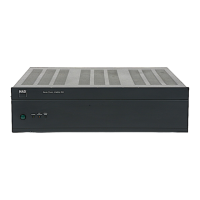
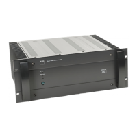
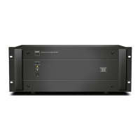
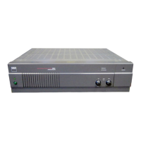
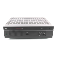
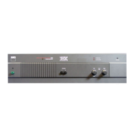
Identifies the power switch, power indicator, soft clipping, and bridge mode indicators.

Rear Panel Connections

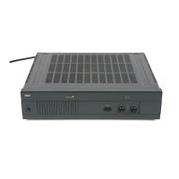
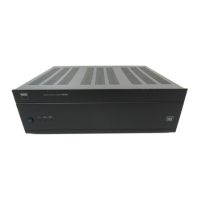
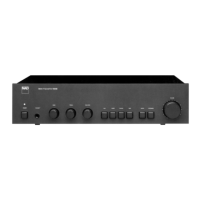
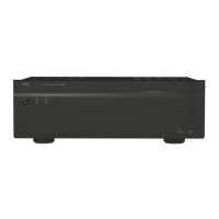
Details the bridge mode switch, input jacks, soft clipping switch, speaker terminals, and AC power cord.

PCB Layout Diagrams

Exploded View Parts List

Exploded View Assembly

Wiring Diagram

Schematic Diagrams

Schematic Diagram (Model 214)

Detailed schematic for the 214 Power Amplifier.

Schematic Diagram (Model 216)

Detailed schematic for the 216 Power Amplifier.

Electrical Parts List

Alignment Procedure

Packing Diagram

Related product manuals