Do you have a question about the NAD 2400 and is the answer not in the manual?
Outlines general safety rules, including using correct parts and restoring original lead dress for safe operation.
Details cold and live leakage tests to ensure product safety before customer return, specifying acceptable limits.
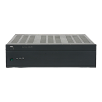
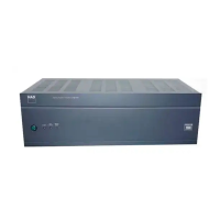
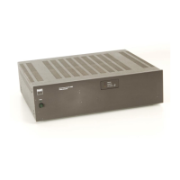
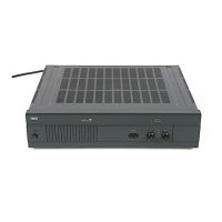
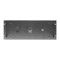
Identifies and describes each connection port on the rear panel, including AC input, speaker outputs, and inputs.
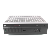
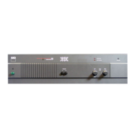
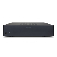
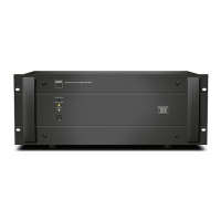
Identifies and describes each control knob, button, and status indicator on the front panel.
Details RMS power output per channel into various impedances, measured according to EIA standards.
Specifies IHF dynamic headroom and peak power capabilities at 8 ohms for stereo mode operation.
Outlines frequency response across inputs and describes infrasonic/ultrasonic filter characteristics.
Lists THD, SMPTE IM, and IHF IM distortion, plus signal-to-noise ratio for stereo operation.
Details continuous average power output and dynamic power in bridged monophonic mode.
Specifies IHF dynamic headroom for the bridged monophonic mode.
Lists the physical dimensions, net weight, and shipping weight of the amplifier unit.
Provides information on the power consumption and voltage ratings of the amplifier unit.
Provides crucial preparatory notes and safety advice before performing amplifier alignment procedures.
Details the procedure for checking and verifying the center voltage of the main amplifier circuit.
Explains how to adjust the idle current for optimal performance of the main amplifier.
Outlines the final steps for completing the main amplifier alignment process.
Presents the detailed electrical schematic diagram for the amplifier's internal circuitry.
Illustrates the physical layout of various printed circuit board assemblies within the amplifier.
Displays the complete wiring diagram showing interconnections between components and assemblies.
Provides an exploded view illustration of the amplifier's internal and external components for assembly reference.
Lists all parts shown in the exploded view with their corresponding part numbers and descriptions.
Lists the electrical components for the main/supply PCB assembly, including part numbers and symbols.
Lists electrical components specific to the mains input PCB assembly.
Details electrical parts for power, soft/protect, and overload indicator assemblies.
Lists electrical components mounted directly onto the amplifier chassis.
| Total Harmonic Distortion | 0.03% |
|---|---|
| Power Output | 100 watts per channel into 8 ohms |
| Frequency Response | 20Hz to 20kHz |
| Input Sensitivity | 1.0V |
| Speaker Load Impedance | 4 to 8 ohms |