Do you have a question about the NAD 2100 and is the answer not in the manual?
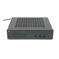
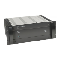
Connection for AC power cord and switched/unswitched outlets.
Controls for input selection, impedance, and operational modes.
Connections for Speaker A and Speaker B outputs.
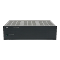
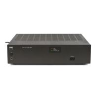
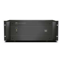
Power switch and status indicator lights.
Controls for input level and soft clipping.
Performance metrics for stereo operation, including power, distortion, and frequency response.
Performance metrics for bridged mono operation, including power and headroom.
Dimensions, weight, and power consumption details.
Details the AC input, power switch, and outlet wiring.
Shows connections between Main PCB, Switch PCB, and Display PCB.
Wiring for speaker outputs, impedance selector, and power terminals.
Precautions before starting amplifier adjustments.
Procedure to verify output DC offset voltage.
Steps to set quiescent current for amplifier channels.
Final checks and re-adjustment after initial setup.
Visual representation of component placement on the left PCB section.
Visual representation of component placement on the right PCB section.
Labels for specific components and important operational notes.
Diagram of power supply and input signal path.
Circuitry for amplification and output stages.
Schematics for control logic and protection systems.
Details various capacitors and resistors with specifications.
Lists switches, fuses, AC sockets, and terminals.
Includes wiring types, labels, and other small parts.
Exploded view showing chassis, plates, and covers.
Visual breakdown of front and rear panel assemblies.
Diagram of internal components, heat sinks, and mounting hardware.
List of parts for chassis, covers, and panels.
Details heat sinks, bezels, and power transformer.
Comprehensive list of screws, nuts, and washers.
List of protective materials like poly-lon and EPE bags.
Includes the main shipping carton and owner's manual.
| Total Harmonic Distortion | 0.03% |
|---|---|
| Damping Factor | 100 |
| Gain | 29 dB |
| Input Impedance | 20 kΩ |
| Frequency Response | 20Hz to 20kHz |
| Dimensions | 420 x 123 x 370mm |
| Power Output | 100 watts per channel into 8 ohms (20dBW) |