Do you have a question about the NAD 2200 and is the answer not in the manual?
| Total Harmonic Distortion | 0.03% |
|---|---|
| Gain | 29 dB |
| Power Output | 100W per channel into 8Ω |
| Frequency Response | 20Hz to 20kHz |
| Speaker Load Impedance | 4Ω - 8Ω |
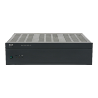
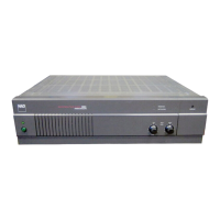
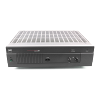
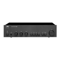
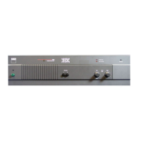
Description of front panel buttons, indicators, and their functions.
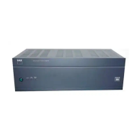
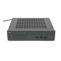
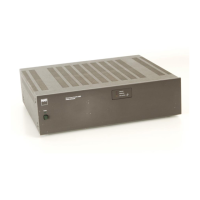
Details of rear panel input/output terminals and power connections.
Step-by-step guide for calibrating and adjusting the amplifier's performance.
Diagram illustrating the internal component connections and layout.
Wiring configurations for UK, Europe, and Australia versions.
High-level functional overview of the amplifier's internal circuitry and signal flow.
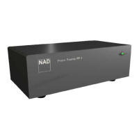
Block diagram for power transformer and voltage selection for different versions.
Detailed schematic and PCB layout for the input signal processing section.
Schematics and PCB layouts for LED indicators and power status.
Schematics and PCB layouts for the fuse protection circuits.
Specific fuse and power connection layouts for different regional versions.
Detailed schematic and layout for the power supply and protection circuitry.
Detailed schematic for the Left channel power amplifier stage.
Detailed schematic for the Right channel power amplifier stage.
Illustrated exploded view showing the physical assembly of the amplifier unit.
Comprehensive list of all parts used in the amplifier unit, with reference numbers.
Detailed listing of capacitors and resistors with specifications.
Detailed listing of semiconductors, relays, connectors, and other components.
Identification and physical placement of main Printed Circuit Boards (PCBs).
Instructions for changing the unit's voltage setting for different regions.