Do you have a question about the NAD 5220 and is the answer not in the manual?
Details the fixed and variable output jacks and the AC power cord connection.
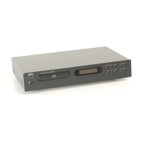
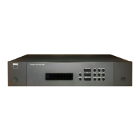
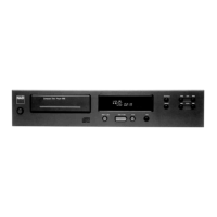
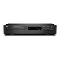
Lists and describes the functions of the front panel controls for both models.
Provides detailed technical specifications including type, channels, frequency response, power, and dimensions.
Step-by-step guide for removing the top cover of the unit.
Instructions for removing the disc tray panel and its associated components.
Details the process of removing the front panel, including screws and connectors.
Step-by-step instructions for detaching the main mechanism assembly.
Specific instructions for removing the clamper lever, including a repair tip.
Detailed procedure for removing the disc tray from the mechanism.
Instructions on how to correctly mount the disc tray onto the mechanism.
Important warnings and considerations for safely removing the disc tray.
Steps to remove the laser pickup, including short-circuiting precautions.
Safety and handling guidelines for replacing the laser pickup.
Instructions for correctly mounting the disc table using spacers.
Illustrates the overall system architecture and signal paths between major components.
Visual representation of the TC9154AP IC pin assignments and internal structure.
Detailed explanation of each pin's function and connection for the TC9154AP IC.
Lists and describes the function of each terminal for the TD6720N IC.
Shows the pin configuration and internal block diagram of the TD6720N IC.
Details the pin names, input/output types, and functions of the TMP4270N IC.
Illustrates the internal architecture and signal flow within the TMP4270N IC.
Shows the pin configuration and internal block diagram of the TMP47C420AF IC.
Lists and describes the function of each pin for the TMP47C420AF IC.
Details pins related to LCD segment and common driver outputs.
Describes pins for system control, interface, and other functions.
Explains pins for LCD control, sync, mute, and key scan operations.
Details pins related to remote control input and timer play functionality.
Identifies key test points and components for various adjustments.
Procedures for focus DC offset, focus balance, and tracking offset adjustments.
Procedures for tracking error balance and analog output offset adjustments.
Steps to adjust the Constant Data Rate (CDR) output level.
Identifies components on the Display P.C. Board.
Shows component placement on the Main P.C. Board.
Locates components on the Mechanism and Power Switch P.C. Boards.
Detailed schematic of the main electronic circuits.
Schematic section for the microcomputer and associated integrated circuits.
Identifies components on the Display and Compressor P.C. Boards.
Shows component placement on the Main P.C. Board.
Locates components on the Mechanism and Power Switch P.C. Boards.
Detailed schematic of the main electronic circuits for the 5240 model.
Schematic section for the microcomputer and associated integrated circuits.
Illustrates the assembly of the disc player mechanism with numbered parts.
Shows the assembly of the player's cabinet with numbered parts.
Lists part numbers for cabinet and mechanism components.
Lists ICs, transistors, and diodes with part numbers.
List of capacitors with part numbers, descriptions, and specifications.
List of resistors with part numbers, descriptions, and values.
List of included accessories such as manuals and cords.
| Type | CD Player |
|---|---|
| Digital-to-Analog Converter | 16-bit |
| Frequency Response | 20Hz - 20kHz |
| Signal-to-Noise Ratio | 100 dB |
| Output Level | 2V |
| Dynamic Range | 95 dB |
| Channel Separation | 90 dB |
| Power Consumption | 15 W |