Do you have a question about the NAD C 541 and is the answer not in the manual?
Important safety cautions including laser and electrical hazards.
Identifies the unit as a Class 1 Laser Product.
Details fuse types and caution for replacement to prevent fire risk.
Outlines checks for insulation and leakage current before customer return.
Details audio performance, decoding, filters, and digital error correction.
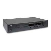
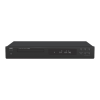
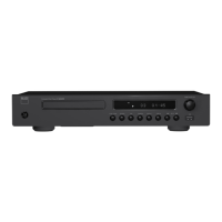
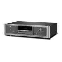
Lists front panel controls and unit physical dimensions and weight.
Identifies LINE OUT, DIGITAL OUT, and NAD LINK connections.
Details POWER, DISC DRAWER, DISPLAY, and playback controls.
Step-by-step guide for removing side and top covers.
Describes steps for testing RF patterns using an oscilloscope.
Illustrates good and poor eye patterns for signal quality assessment.
Critical instructions for preventing electrostatic discharge (ESD) damage.
Precautions to avoid eye exposure to the laser beam during operation.
Details methods to protect laser diodes from static damage during replacement.
Diagram showing component placement on the Live PCB.
Diagram showing component placement on the Key PCB.
Diagram showing component placement on the Display PCB.
Functional blocks of the LA9240 IC.
Functional blocks of the LC78621ED IC.
Lists PCB assemblies, resistors, switches, capacitors, transformers, and fuse assembly.
Details fuse types and lists various capacitors.
Continues the list of capacitors with detailed specifications.
Lists diodes, coils, crystals, jacks, transistors, and resistors.
Continues the list of resistors with their specifications.
Lists all integrated circuits used in the unit with part numbers.
Visual breakdown of the CD mechanism components.
Visual breakdown of the laser pickup assembly components.
| Type | CD player |
|---|---|
| Frequency Response | 20 Hz - 20 kHz |
| Total Harmonic Distortion | < 0.003% |
| Channel Separation | >90dB |
| Output Impedance | 100 ohms |
| Digital Output | Coaxial |
| Output | 2.0 V |