Do you have a question about the NAD C 565BEE and is the answer not in the manual?
Important safety precautions and laser product information.
Procedures for replacing fuses and performing safety checks.
Technical audio performance specifications.
Electrical power consumption and physical size details.
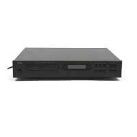
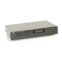
Identification of rear panel ports and connectors.
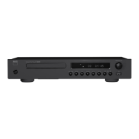
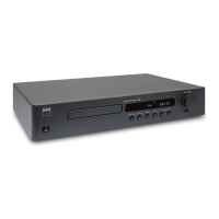
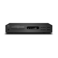
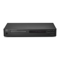
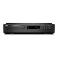
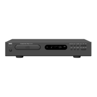
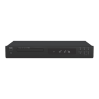
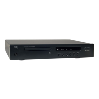
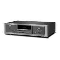
Identification of front panel buttons, display, and inputs.
Step-by-step guide for removing outer panels.
Diagram showing mainboard, servoboard, and power interfaces.
Illustration of wiring between internal boards and components.
Methods and oscilloscope settings for RF signal pattern testing.
ESD protection for optical pickup and laser beam safety.
Essential ESD safety steps for replacing the laser pick-up assembly.
Table and notes on special key combinations for advanced functions.
Component and trace layout for the main printed circuit board.
Layouts for Power, Vol, LED, USB, and VFD circuit boards.
Layouts for the servo board, top and bottom views.
Detailed schematic for the Digital-to-Analog Converter section.
Schematics for MCU, RS232, Trigger In, and IR In circuits.
Circuit diagram detailing the unit's power supply system.
Schematics for the front panel's user input and display elements.
Detailed schematic for the servo motor control and drive systems.
Schematic illustrating the USB controller and its data connections.
Block diagrams for various voltage regulator and buffer ICs.
Block diagram of SRC4382's audio serial port and host interfaces.
Block diagram detailing MCU peripherals and memory organization.
Block diagrams for EEPROM and voltage regulator ICs.
Block diagrams for motor driver, op-amps, and comparator ICs.
Block diagrams for power board shunt regulator and control IC.
Diagram of DSP core, CPU interface, and memory blocks.
Block diagram showing MCU peripherals and memory controller.
Block diagrams for servo board regulator, EPROM, and analog ICs.
Circuit diagram for the MM1669AH motor driver IC.
Steps to diagnose and resolve power, tray, and playback problems.
Exploded view of the laser assembly, motors, and spindle components.
Exploded view of the main chassis, front panel, and enclosure parts.
Diagram and list of items included in the product packaging.
| Frequency range | 20 - 20000 Hz |
|---|---|
| Audio formats supported | MP3, WMA |
| Signal-to-Noise Ratio (SNR) | 118 dB |
| Total Harmonic Distortion (THD) | 0.01 % |
| CD changer | No |
| Device type | Personal CD player |
| MP3 playback | Yes |
| Product color | Graphite |
| Disc loading type | Tray |
| Channel separation | 90 dB |
| Volume control | Digital |
| USB 2.0 ports quantity | 1 |
| Package weight | 6600 g |
| Depth | 285 mm |
|---|---|
| Width | 435 mm |
| Height | 70 mm |
| Weight | 5200 g |