The provided document is a service manual for the NAD 5240/5220 Compact Disc Players. This manual covers all versions, including those for North America (A), Canada (C), Europe & Others (E), UK (U), and Australia (Y).
The NAD 5240/5220 are compact disc players designed for high-fidelity audio playback. They utilize an optical pickup system to read 16-bit linear, 2-channel (stereo) audio data from compact discs.
Key Technical Specifications:
- Type: Compact Disc Player with optical pickup
- Quantization: 16 bit linear
- Channels: 2 channels (stereo)
- Frequency response: 5 Hz – 20 kHz ±0.5 dB
- Dynamic range: 94 dB
- Total harmonic distortion: 0.004% (1 kHz)
- Channel separation: 90 dB
- Wow and flutter: Unmeasurable
- Output: 2.0 Volts
- Pickup: Semiconductor laser
- Track search: By track number
- Power consumption: 13 Watts
- Dimensions: 340(W) x 57.5(H) x 309.5(D) mm
- Weight: 2.9 kg
Usage Features:
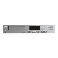
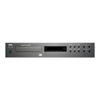
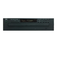
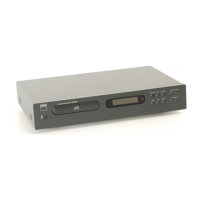
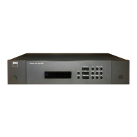
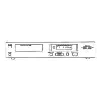
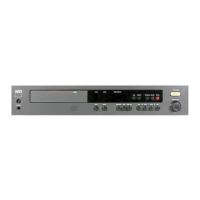
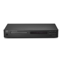
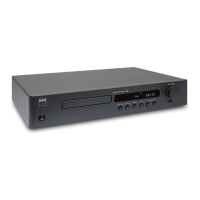
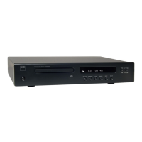
The front panel of the NAD 5240 (and a simplified version for the 5220) offers a comprehensive set of controls for disc playback and navigation:
- Power On/Off (1): To turn the unit on or off.
- Disc Drawer (2): The tray where the compact disc is placed.
- Open/Close (3): To open and close the disc drawer.
- Play/Pause (4): To start or temporarily stop playback.
- Reset (5): To reset playback or settings.
- Skip Forward/Back (6): To navigate between tracks.
- Scan Forward/Back (7): To quickly scan through the audio on a track.
- Display Selector (8): To change the information shown on the display.
- Memory (9): For programming tracks or storing settings.
- Repeat (10): To repeat the current track or disc.
- CDR (Controlled Dynamic Range) (11): (5240 only) This feature likely allows for dynamic range compression, useful for listening at lower volumes or in environments where wide dynamic range might be disruptive.
- Status Indicators (12): Lights or display elements to show the current operational status.
- Timer Play (13): (5220 only) Suggests a function to start playback at a set time, possibly in conjunction with an external timer.
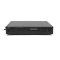
The rear panel includes:
- Output Jacks (1):
- Fixed (1a): Standard fixed-level audio output.
- Variable (1b): (5240 only) Allows for adjustment of the output level, potentially useful for direct connection to a power amplifier without a preamplifier.
- AC Line Cord (2): For connecting the player to mains power.
Maintenance Features (Disassembly and Adjustment):
The service manual provides detailed instructions for various maintenance and repair procedures, indicating that the device is designed for serviceability by qualified personnel.
Disassembly Instructions:
- Top Cover Removal: Involves removing two screws from the top cover side boards and four screws from the bottom.
- Tray Panel Removal: Requires removing the top cover, lifting a mechanism assembly clamper lever, pulling out the disc tray, and releasing two hooks.
- Front Panel Removal (with Display P.C. Board): After removing the top cover and tray panel, four screws from the side and three from the bottom are removed.
- Mechanism Assembly Removal: Involves removing the tray panel, five screws, and two connectors.
- Clamper Lever Removal: Instructions are provided for pushing a hook with a minus driver and for replacing a broken hook with a screw and washer.
- Disc Tray Removal: Details how to lift the clamper lever, pull the disc tray, and push a mechanism main chassis hook. The manual notes two types of mechanism chassis with different removal procedures.
- Laser Pickup Removal: Requires short-circuiting the Laser Pickup P.C. Board pattern, removing six screws and two connectors.
- Cautions on Laser Pickup Removal/Replacement: Emphasizes the importance of soldering and short-circuiting terminals to protect the laser pickup from damage, disconnecting leads after soldering, avoiding touching pickup terminals, connecting leads before unsoldering for replacement, using a grounded soldering iron, covering the workbench with a conductive mat, and discharging static electricity from the body before handling components.
- Disc Table Mounting: Instructions for inserting a spacer between the main chassis and disc table, ensuring it touches the spacer, and mounting it parallel to the main chassis. Notes that there are three kinds of spacer jigs corresponding to different motor assemblies or pickups.
Adjustment Procedures (After Laser Pickup Replacement):
- Focus DC Offset Adjustment: Involves setting the unit to STOP mode, connecting an oscilloscope or tester across TP-FEO and TP-VREF, and adjusting R329 to obtain 0±10mV DC offset.
- Focus Balance Adjustment: Requires connecting an oscilloscope across TP-RF and TP-VREF, playing a YEDS-7 test disc, and adjusting R332 to maximize the 3T component of the RF signal.
- Tracking Offset Adjustment: Similar to focus DC offset, but involves connecting an oscilloscope or tester across TP-TSO (TE signal) and TP-VREF, and adjusting R315 to obtain 0±10mV DC offset.
- Tracking Error Balance Adjustment: Involves connecting an oscilloscope across TP-TSO (TE signal), playing a YEDS-7 test disc, short-circuiting leaf switch S102, pushing PLAY, releasing the short circuit, and adjusting R305 to obtain 0V DC offset for the tracking error signal. The STOP key is pressed after adjustment.
- Analog Output Offset Adjustment: (Not necessary when pickup is replaced) Involves turning on the unit, connecting a DC voltmeter or oscilloscope to specific pins on the Main P.C. Board, and adjusting semi-fixed resistors R545 and R546 to obtain 0±10mV DC range offset.
- CDR Adjustment: (5240 only) Involves playing track No. 20 of a YEDS-7 test disc, connecting an AC level meter to the FIXED output jack, setting the level to 0dB with the CDR switch OFF, and adjusting R601 and R602 until +6dB (twice the output obtained with CDR switch OFF) is achieved with the CDR switch ON.
- Volume Adjustment: The manual states that volume adjustment attached to pickup adjustment is completed, implying it's part of a broader calibration.
The manual also includes block diagrams, IC terminal functions, electrical parts locations, wiring diagrams, schematic diagrams, and exploded views of the mechanism and cabinet, along with a comprehensive parts list. These resources are crucial for detailed troubleshooting and component-level repair. Special caution is noted for components marked with an oval in the schematic and parts list, indicating they have special safety characteristics and should only be replaced with identical types.