Do you have a question about the NAD T748 and is the answer not in the manual?
Essential guidelines for safe and correct product servicing and handling.
Important safety measures and procedures to follow during service.
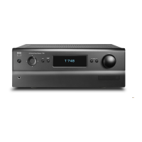
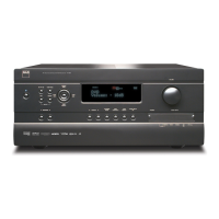
Detailed technical data and performance characteristics of the AV receiver.
Procedures and instructions for taking the unit apart for servicing.
Identifies the main internal components and their positions within the unit.
Visual breakdown of the unit's parts and their assembly order.
Block diagram and pinout for the STM32F103ZET6 microcontroller.
Block diagram and pin configuration for the R2A15218FP IC.
Block diagram and pin description for the MX29LV32DTTI flash memory.
Device block diagram for the TMS320DA788B audio DSP.
Typical connection diagram and pin description for the CS42528 CODEC.
Pin configuration for the NJW1321FP1C IC.
Pin function and description for the A3V64S40ETP-G6 SDRAM.
Pin and package information for the ADV7511KSTZ HDMI transmitter.
Pin configuration and function descriptions for the ADV7844KBCZ IC.
Pin out diagram for the TPS65251RHAR power management IC.
Pin assignment and logic symbol for the TC74VCX541FT bus buffer.
Pin configuration and description for the AZ4580M operational amplifier.
Pin connection and pin description for the ST3232ECDR RS-232 transceiver.
Overall wiring connections and the schematic for the front board.
Schematics for MCU, DSP, Audio, and DAB sections.
Schematics for power, video, HDMI, and amplifier circuits.
Schematics for the main, sub, and pre-amplifier boards.
Visual layouts of the front, input, main, sub, and HDMI circuit boards.
Step-by-step guide for diagnosing and resolving HDMI section issues.
Guide for troubleshooting audio output problems in digital and analog paths.
Procedures for diagnosing issues with the unit's LED indicators and VFD display.
Explanation of part numbering conventions for resistors and capacitors.
Comprehensive list of part numbers, descriptions, and specifications for components.
| Frequency range | 20 - 20000 Hz |
|---|---|
| Input sensitivity | 250 mV |
| Audio output channels | - channels |
| Signal-to-Noise Ratio (SNR) | 100 dB |
| Total Harmonic Distortion (THD) | 0.08 % |
| Dynamic power per channel (4 Ohm) | 160 W |
| Dynamic power per channel (8 Ohm) | 110 W |
| Power output per channel (20-20KHz@8 Ohm) | 80 W |
| HDMI in | 4 |
| Line-in | Yes |
| Audio (L/R) in | 3 |
| Composite video in | 2 |
| S-Video inputs quantity | 1 |
| Connectivity technology | Wired |
| Speakers connectivity type | Binding post |
| Ethernet LAN | No |
| AM band range | 520 - 1710 kHz |
| FM band range | 87.5 - 108 MHz |
| Supported radio bands | AM, DAB+, FM |
| Display | - |
| Product color | Black |
| Apple docking compatibility | Not supported |
| Sustainability certificates | ENERGY STAR |
| AC input voltage | 120 V |
| AC input frequency | 60 Hz |
| Power consumption (standby) | 0.5 W |
| Power consumption (typical) | 50 W |
| Package weight | 14000 g |
| Depth | 387 mm |
|---|---|
| Width | 435 mm |
| Height | 167 mm |
| Weight | 11500 g |