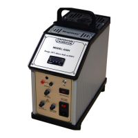
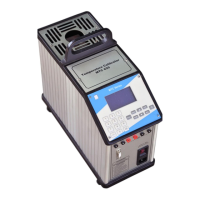
The Nagman 650-H is a medium temperature dry block calibrator designed for calibrating various temperature sensors and devices.
Function Description
The Nagman 650-H is used for calibrating RTDs, thermocouples, temperature switches, and temperature indicators. It incorporates a Nagman 172 temperature controller, which features a two-level temperature profile for RAMP and SOAK between the set temperature point (SP) and set time. During calibration, the "RUN" indicator on the controller remains active, continuously displaying the current block temperature. The desired temperature is set using the "P" key to access input parameters and the ▲/▼ keys to adjust the value. Proper use of the instrument ensures accurate calibration of temperature sensors.
Important Technical Specifications
- Range: 50°C to 650°C
- Resolution: 0.1°C
- Accuracy: ±1.2°C
- Stability: ±0.5°C
- Stabilisation Time: 15 Minutes
- Well Diameter: 30 mm
- Immersion Depth: 110 mm
- Heating Time (Ambient to max.): 20 Minutes approx.
- Cooling Time max. (to 100°C): 60 Minutes
- Switch Test facility: Provided
- Interchangeable Thermowells: Single hole to suit 1/4" & 1/2" Probes. Other Sizes / Multihole available as optional.
- Housing / Mounting: Bench-top
- Power Supply: 230V AC, 50 Hz (Optional 115V AC, 60 Hz)
- Instrument Dimensions (L x D x H): 160 x 330 x 350 mm
- Instrument Weight (approx.): 8.5 Kg.
- Operating Temperature Range (Ambient): 15-40°C
- Storage Temperature Range: 10-50°C
- Humidity Range: 40-75%RH
- Protection Class: IP52
Usage Features
Standard Delivery
The standard package includes the basic instrument, test leads, mains cable, insertion tubes (to suit 2x1/4" & 1x1/2" probes), a tool for insertion tubes, spare fuses, a carrying case, a traceable calibration certificate, and an instruction manual.
Optional Accessories
Optional accessories include additional thermowells/insertion tubes (single hole standard sizes to suit 1/8", 1/4", 3/8”, 1/2", 3/4" & 3, 4, 5, 6, 7, 8, 10, 12, 13, 15, 17, 19 & 21 mm probes; multihole typical configurations like (1x6 + 1x8) or (3x6) or (1x10 + 1x4) mm), computer interface, "Caltemp" calibration software, reference thermocouple, dual voltage selection (110V & 230V AC), and power supply 110V AC, 60 Hz. Calibration Certificates are issued in accordance with NABL per ISO/IEC 17025:2017 Standards.
Parts Identification
The device features a heater block, PID controller, computer interface, switch test points, control fuse, selector switch, heater fuse, transformer fuse, and a main switch.
Connection Diagram
The calibrator connects to a temperature sensor (UUT) and a measuring instrument (for UUT) to perform calibration.
Safety Instructions
- General Safety: Designed for interior use only. Inspect for damage before each use. Do not use if damaged or operating abnormally. Use according to design to prevent damage. Do not place under cabinets; allow clearance for probe insertion/removal. Do not drop probes into the well to avoid sensor shock. Use only for calibration work. Do not operate near flammable materials. Use only by trained personnel. Unattended operation is not recommended.
- Temperature Safety: Handle thermometer probes with care as they are sensitive. Do not leave inserts in the instrument for prolonged periods at high temperatures to prevent damage. Do not slam probe sheaths into the well. Do not operate in wet, oily, dusty, dirty, or explosive environments. Operate at room temperature (10°C to 40°C) with at least 20 cm air circulation around the instrument. Continuous high-temperature operation may shorten component life. Use caution at high temperatures (above 650°C) to prevent fires and burns. Do not turn off the instrument above 100°C; cool to below room temperature first. Do not use if the cooling fan is out of order. Ensure free air supply to the fan grill.
- Electrical Safety: Ensure earth connection and proper power cord plug-in. Plug into a 230V AC, 50Hz (or optional 115V AC, 60Hz) grounded outlet. The power cord has a three-pin grounding plug; use a properly grounded three-pin socket. Do not use extension cords or adapter plugs. Replace fuses with the same rating, voltage, and type. Replace power cords with approved cords of correct rating. Turn off immediately during power fluctuations. Do not remove the fuse box until the power cord is disconnected. Return to manufacturer if fuses blow immediately after replacement.
- Handling Hot Parts: Do not touch the well access surface. The block vent may be very hot. Do not touch the well or insert while heating. Do not touch the tip of the sensor (or immersed portion) when removed from the insert/well. Air over the well can reach >200°C. Insert/remove probes and inserts only when the instrument is below 50°C. Use extreme care when removing hot inserts. Do not touch the calibrator handle during use, as it may be hot.
Operating Instruction
- Display Panel: The display shows AT (tuning process), OUT (relay/pulse control output), RUN (controller active), ALM (alarm active), and COM (RS485 activity).
- Parameter Configuration: The display alternates between parameter prompt and its blinking value.
- P Key: Used to navigate menu parameters. Pressing and holding "P" for 2 seconds jumps to the next parameter level.
- ▲/▼ Keys: Used to increment/decrement parameter values.
- F Key: Accesses special functions like RUN (toggles YES/NO) and timer control modes (factory configured, not for calibration).
- Set Point/Unit Procedure:
- Connect power cable and switch ON.
- Press "P" to access input parameter ("RUN 0.00").
- Press "P" again to enter set point ("SP 0.00").
- Use ▲/▼ keys to set desired temperature.
- Long press "P" until "PASS" is displayed to save and start heating.
- Insert sensors into the corresponding insert hole.
- Allow the bath to stabilize.
- Connect test probe to indicator and record readings. Repeat for other calibration points.
- After calibration, set bath temperature to ambient and allow to cool.
- Switch off power supply once ambient temperature is reached.
- Unit Change (°C to °F):
- Hold "P" key until "type" parameter is displayed.
- Release "P" and press it repeatedly until "unit" is displayed.
- Release "P". Display shows "°C".
- Use ▲/▼ keys to change to "°F".
- Long press "P" until "PASS" is displayed to save.
- Repeat to change back to "°C".
- Note: The "F" key is not to be used in this temperature instrument during calibration.
- Special Notes: All parameters are factory configured. Users should only change "SET point" and "UNIT". Meddling with other functions may cause malfunction, overheating, or hazards. If stuck during configuration, exit without entering "P" key.
- Switch Test: Connect thermostat switch output to test sockets. For "Normally Closed" switches, LED glows and stops when state changes. For "Normally Open" switches, LED does not glow initially and glows when state changes.
Maintenance Features
Maintenance
- Cleaning: Switch off, cool down, and remove all cables before cleaning. Clean the exterior with water and a soft, wrung-out cloth. Ensure no water penetrates the calibrator.
- Insert: Keep the insert clean and regularly wipe with a soft, lint-free, dry cloth. Ensure no textile fibers are on the insert when inserted into the well, as they may adhere to the well and cause damage.
Adjusting and Calibrating
It is advised to return the calibrator to Nagman, Chennai, or an accredited laboratory at least once a year for calibration.
Returning for Service
When returning the calibrator for service, provide complete information about the problems faced for clear analysis. The calibrator should be returned in its original packing.
Troubleshooting
- Main Fuse Replacement: Identify the main fuse in the fuse box. Open the lid with a screwdriver. Replace with a 6.3A fuse (12A for 115V).
- Controller Not ON: Check the control fuse.
- Fan Not Working: Check the transformer fuse.
- Heater Fuse Replacement: Identify the heater fuse in the fuse holders. Open the fuse holder anti-clockwise. Replace with a 6.3A fuse (12A for 115V).
Nagman's Liability
Nagman's liability ceases if parts are replaced/repaired using non-recommended spare parts. Liability is restricted to errors originating from the factory.