EZvav Controllers:
These are brief instrucons for installing a
EZvav controller.
For complete details, download IOM
“IOM-EZVAVINST” from Nailor website.
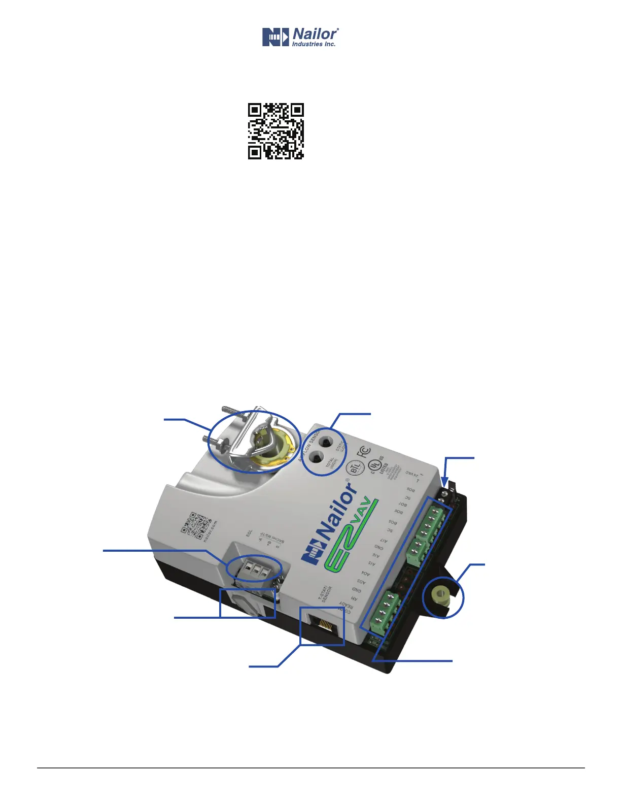
1 Align the damper and drive hub
Manually rotate the damper on the VAV box to the fully closed
posion.
Press the gear clutch buon and rotate the drive hub in the same
direcon that closed the damper. Turn the hub unl it reaches a
stop, then rotate the hub back 2 degrees and release clutch.
2 Mount the controller to the VAV box
Place the controller over the damper sha.
Finger ghten the nuts on the V-bolt to posion the sha in the
drive hub.
Center the mounng bushing in the mounng tab and fasten it
with a #8 sheet metal screw.
Evenly ghten the V-bolt nuts on the drive hub to 30-35 in-lbs.
3 Connect the room sensor cable
Connect a EZvav sensor to the controller with a standard Ethernet
cable. Plug the controller end of the cable into the T’stat connector.
4 Connect the airow sensors
Connect the airow sensor on the VAV box to the airow ports on
the controller. Use 0.25 in. FR tubing.
5 Connect auxiliary equipment (oponal)
Other VAV equipment such as fans, heaters, reheat valves, and
discharge air temperature sensors connect at the green terminals.
If the controller is part of a BACnet network, wire it to the gray
MS/TP network terminals.
6 Connect 24 volt power
Connect the controller to a 24 volt, Class 2 transformer at the black
power terminals. As soon as power is connected, the controller
begins operaon.
IOM-EZVAVQSIG
Date: 9-2015 Supersedes: NEW
Page 3 of 4
www.nailor.com
Quick Start Installation Guide – EZvav Sensors & Controllers
Nailor reserves the right to change any information concerning product or specification without notice or obligation.
Drive Hub
and V-bolt
Airow Sensor
Ports
Gear Clutch
Buon
Mounng Tab
and Bushing
Room Temp. Sensor/
T’stat connector
Black Power
Terminals
Green Terminals for
Fan, Reheat and
Other Equipment
Gray Network
Terminals