Do you have a question about the Nakamichi RX-202E and is the answer not in the manual?
Check tape guide height for record/playback and erase heads.
Checks the head base stroke for proper alignment and clearance.
Aligns and checks the azimuth and height of the record/playback head.
Adjusts the pressure roller for correct torque and tape contact.
Adjusts slide base position on the logic PCB for cassette case alignment.
Verifies tape path stability and head contact during playback.
Adjusts reel motor speed to specified torque in play mode.
Calibrates tape speed by adjusting the capstan motor volume.
Specifies lubricants for tape transport mechanism parts upon replacement.
General instructions and table for performing electrical adjustments and measurements.
Adjusts playback frequency response using specific tapes and settings.
Checks Dolby NR circuit operation for B-Type and C-Type.
Exploded view and parts list for the overall unit synthesis.
Lists parts and diagrams for the main chassis assembly.
Parts list and diagram for the rear panel assembly.
Parts list and diagram for the synthesis mechanism assembly.
Lists parts and diagrams for the 'S' mechanism assembly.
Lists parts and diagrams for the 'RS' mechanism assembly.
Exploded view and parts list for the main mechanism assembly.
Parts list and diagram for the motor holder assembly.
Parts list and diagram for the 'S' slide chassis assembly.
Exploded view and parts list for the main chassis assembly.
Diagram and parts list for the power switch printed circuit board.
Diagram and parts list for the shut-off printed circuit board.
Diagram and parts list for the lid lamp printed circuit board.
Diagram and parts list for the eject switch printed circuit board.
Diagram and parts list for the tape switch printed circuit board.
Diagram and parts list for the volume printed circuit board.
Diagram and parts list for the control switch printed circuit board.
Diagram and parts list for the fader printed circuit board.
Diagram and parts list for the counter printed circuit board.
Diagram and parts list for the main printed circuit board.
Diagram and parts list for the logic printed circuit board.
Safety and parts replacement guidelines for service technicians.
Block diagrams illustrating integrated circuit functions and pin configurations.
Schematic diagram detailing the audio amplifier circuitry.
Schematic diagram for the cassette deck's mechanism control system.
Charts detailing the operational timing sequence of various functions.
Graphs showing equalization and amplifier frequency response curves.
Block diagram of the audio amplifier section's signal flow.
Block diagram of the mechanism control system's operation.
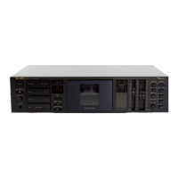
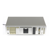
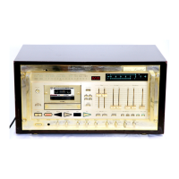
| Brand | Nakamichi |
|---|---|
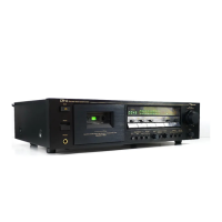
| Model | RX-202E |
| Category | Cassette Player |
| Language | English |