NAPCO StarLink Fire: Getting Started Guide 39
TECHNICAL SPECIFICATIONS
Radiation Pattern ........ Omni-Directional
Gain ............................. 4-9dBi
Bandwidth ................... VSWR: <1.5: 1 = 695-3000
MHZ in all 3G & 4G Bands
..................................... VSWR: <2.0: 1 = 695-3000
MHZ
Impedance ................... 50 ohms
Max. Input Power ........ 50 watts
Exterior Finish ............ Black UV stable
Dimensions ................. 8⅞" (225 mm) Length x 2⅜" (60 mm) od
Weight ......................... 10 oz.
RF Connector .............. Type N female
PIM ............................... -155dBc
Installation .................. Included L Bracket with U-bolts for up to 2" pole
Elements ..................... Copper
Polarization ................. Vertical
Wind Rating ................ > 110 MPH
Warranty ...................... 36 months
Environments: ............ Indoor or outdoor use
333 Bayview Avenue, Amityville, New York 11701
For Sales and Repairs, (800) 645-9445
For Technical Service, (800) 645-9440 or visit us at
http://tech.napcosecurity.com/
(Note: Technical Service is for security professionals only)
Publicly traded on NASDAQ Symbol: NSSC
© NAPCO 2017
WI2230ALF 08/17
StarLink Antenna Extension Kits
StarLink SLE Fire Series UL Listed Communicators
Installation Instructions
The StarLink Antenna Extension Kits are designed to increase cellular transmission signal strength and provide an exterior
antenna option for the StarLink SLE Fire Series UL Listed communicators. The kits include a dual wide band, 4-9dBi omnidi-
rectional indoor / outdoor antenna that enhances transmission and reception signals within the 824 - 894MHz and 1850 -
1990MHz bands, and are designed to minimize loss and maximize gain. The antenna is foam filled for vibration stabilization
and long lasting performance in extreme conditions. A UV stable polyurethane finish provides outstanding corrosion resistance
in the harshest environments. Each antenna includes an L bracket with stainless steel U Bolts for pole or wall mounting.
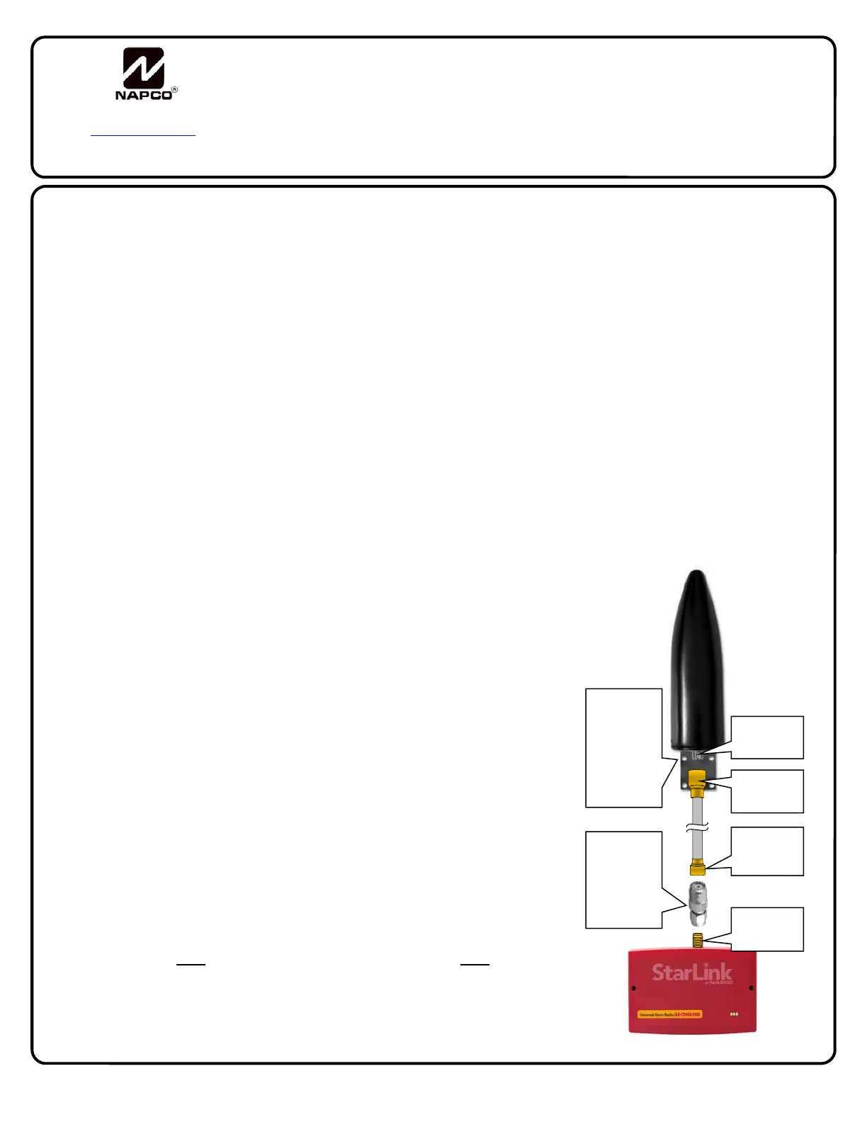
The kits also include high quality, low loss coaxial cable and an adaptor for connection to the SMA female antenna connector
of all StarLink radio models.
ORDERING INFORMATION
SLE-ANT - Antenna only, black UV stable finish
SLE-ANTEXT30 – 30' Antenna Extension Kit, Includes SLE-ANT Antenna,
30' Coax Type N male to MINI-UHF male terminated cable and SMA M to
MINI-UHF F Adaptor
SLE-ANTEXT50 - 50' Antenna Extension Kit, Includes SLE-ANT Antenna,
50' Coax Type N male to MINI-UHF male terminated cable and SMA M to
MINI-UHF F Adaptor
SLE-ANTEXT75 - 75' Antenna Extension Kit, Includes SLE-ANT Antenna,
75' Coax Type N male to MINI-UHF male terminated cable and SMA M to
MINI-UHF F Adaptor
IMPORTANT: DO NOT ALTER OR ADD COAXIAL CABLE! DO NOT PLACE
ANTENNA WITHIN 4 FEET OF OTHER LARGE METAL OBJECTS.
FEATURES
Compact design
UV stable polyurethane finish
Vibration stabilized foam filled
Excellent 700 MHZ LTE performance
VSWR <1.5:1 in 3G & 4G bands
Universal applications
MINI-UHF
Male
Type N
Female
Adaptor
from MINI-
UHF
Female to
SMA Male
SMA
Female
Secure
antenna to
L-Bracket
using
supplied
nut
Type N
Male

 Loading...