StarLink
™
SLE Series Alarm Communicators -- Installation Instructions 5
TB3: PGM1 (–). Normally low output wired to the
(+) of a zone dedicated to monitoring the radio status.
Should be programmed on Napco control panels as
Day Zone, but be programmed to sound locally and
NOT activate the bell. Note: See steps "a" and "b",
below.
For Backup Mode:
Install jumper #3 in jumper block labeled "X5". The wiring
between the control panel and the StarLink radio is over
seven (7) wires, as follows:
TB1: PWR (+12V)
TB2: PWR GND (–)
TB10: TIP
TB11: RING
TB13: PANEL TIP
TB12: PANEL RING
TB3: PGM1 (–). Normally low output wired to the
(+) of a zone dedicated to monitoring the radio status.
Should be programmed on Napco control panels as
Day Zone, but be programmed to sound locally and
NOT activate the bell.
a. Without applying power (voltage), connect to screw
terminals TB1 (+12V) and TB2 (–). If the control
panel Aux. Output cannot supply the necessary cur-
rent, then you must use the SLE-SMTCHG Smart
Charge Module accessory with additional battery
(see WI1946). For wiring connections, see the wir-
ing diagrams further in this manual.
b. Referencing the correct wiring diagram for the ap-
propriate control panel (wiring diagrams are located
further in this manual), connect the "TELCO" control
panel terminals TIP and RING. Do NOT connect
the StarLink radio terminals TB10-13 to house tele-
phone lines (RJ31X modular plug wires, etc.).
STEP 4: APPLY POWER
The StarLink radio requires 12VDC. It draws less than
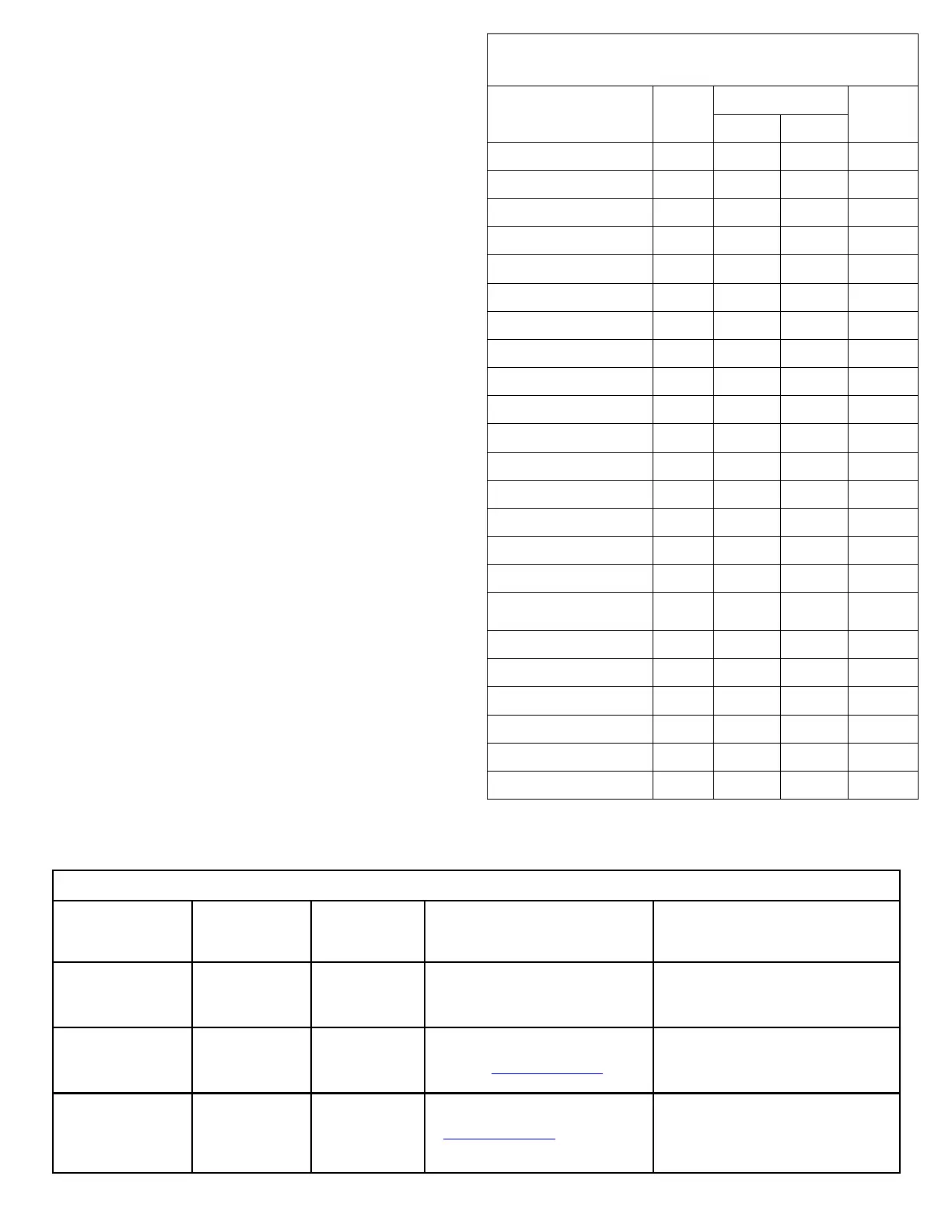
STARLINK RADIO RELATED EVENT
REPORT CODES (Contact ID by default)
EVENT AREA
CONTACT ID
PULSE
4/2
CODE ZONE #
IN 1 Fire 0 E110 990 1A
IN 1 Burg 0 E130 991 31
IN 2 Panic 0 E120 992 22
IN 3 Trouble 0 E300 993 F3
Low Battery/Voltage 0 E302 994 F4
Tamper Trouble 0 E341 995 F5
Line Cut 0 E352 996 F6
Reboot 0 E625 997 F7
IN 1 CO (Carbon Monoxide) 0 E162 998 18
Panic Alarm* E123
Holdup Alarm* E122
Medical Alarm* E100
24 hour Aux. Alarm* E150
24 hour Aux. Restore* R150
Burg Perimeter Alarm* E131
Burg Interior Alarm* E132
Keypad Holdup Alarm
(ambush)*
E121
Keypad Panic Alarm* E123
Keypad Emergency Alarm* E140
Opening* E401
Closing* R401
A.C. Trouble* E301
Tel 1 Fail* E351
*Not generated by the StarLink radio.
NOC Originated
Alarms
Contact ID
Event Data
Sent
Pulse Format
Event Code
Sent
Initiated By Comments
Supervisory Fail E356 A00 Zn000 99
Automatically by NOC if fail to receive
any signal from StarLink radio within
Supervisory Timeout duration.
For Auto Enroll, uses captured telephone
number, Sub ID and format. For Dealer
Programmed, uses entered telephone
number, Sub ID and format.
Press to Send
Test Signal
E601 A00 Zn000 98
Manually by dealer from the Manage-
ment Center Signal Log screen
(located at www.napconoc.com).
Sends test into CS receiver.
Same comment as above.
Press to Send
Radio Test
Not Applicable
Nothing sent to
CS receiver
Not Applicable
Manually by dealer from the Manage-
ment Center Checkins screen (located
at www.napconoc.com). Sends a com-
mand to the StarLink radio to force a
check-in to the NOC.
----
SIGNALS ORIGINATED AT THE NOC
 Loading...