6
W415-0341 / K / 10.05.07
VENT INSTALLATIONS
* A clearance to combustibles of 2" at the vent pipe top
must be maintained. The firestop spacer W010-1777sup-
plied with the unit must be used to maintain this clear-
ance.
** The first 5 1/8" of finishing material above the GD34
must be non-combustible. The header must be steel.
For safe and proper operation of the fireplace follow the
venting instruction exactly.
Deviation from the minimum or the maximum vertical
vent length can create difficulty in burner start-up and/
or carboning.
A terminal shall not terminate directly above a sidewalk
or paved driveway which is located betweeen two sin-
gle family dwellings and serves both dwellings. Local
codes or regulations may require different clearances.
In order to avoid the possibility of exposed insulation or
vapour barrier coming in contact with the fireplace
body, it is recommended that the walls of the fireplace
enclosure be “finished” (ie: drywall/sheetrock), as you
would finish any other outside wall of a home. This will
ensure that clearance to combustibles is maintained
within the cavity.
Wolf Steel, Simpson Dura-Vent, Selkirk Direct Temp and
American Metal Amerivent venting systems must not be
combined.
Purge all gas lines with the glass door of the fireplace
open. Assure that a continuous gas flow is at the burner
before closing the door.
Under extreme vent configurations, allow several minutes
(5-15) for the flame to stabilize after ignition.
Six (6") inches is the minimum bend radius allowed for
the 7" diameter flexible liner.
FOR SPECIFIC VENTING PARAMETERS, REFER TO
PAGES 9-14.
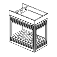
Minimum clearance to combustible construction
from fireplace and vent surfaces:
BGD33 GD33 BGD34 GD34
SIDE OF THE UNIT 0" 0" 0" 0"
BACK OF THE UNIT 0" 0" 0" 0"
BOTTOM OF THE UNIT 0" 0" 0" 0"
TOP OF THE UNIT 0" 0" 0" 5
1
/8"**
TOP OF THE VENT PIPE 2"* 2"* 2" 2"
SIDES OF THE VENT PIPE 1" 1" 1" 1"
BOTTOM OF THE VENT PIPE 1" 1" 1" 1"
RECESSED DEPTH 13" 13" 13" 13"
TABLE 2
ALL MODELS: Vent lengths that pass through unheated
spaces (attics, garages, crawl spaces) should be insu-
lated with the insulation wrapped in a protective sleeve
to minimize condensation.
Provide a means for visually checking the vent connec-
tion to the fireplace after the fireplace is installed.
Do not allow the inside liner to bunch up on horizontal or
vertical runs and elbows. Keep it pulled tight. A 1¼" air
gap between the inner and outer liner all around is re-
quired for safe operation.
Use a firestop, vent pipe shield or attic insulation shield
when penetrating interior walls, floor or ceiling.
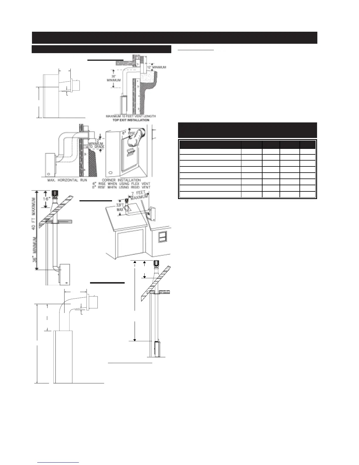
TYPICAL VENT INSTALLATIONS
16”
MINIMUM
40 FT MAXIMUM
3 FT MINIMUM
F I G U R E 4 a - b
FIGURE 3a - b
FIGURES 2a - d
24" MAXIMUM
8" MINIMUM (BGD33)
12" MINIMUM (GD33)
20 1/4"
1" RISE / FT *
* REFER TO "VENTING SECTION"
10” MINIMUM
(BGD34)
24” MINIMUM
(GD34)
53 5/8”
24” MAX
11” MIN
1” RISE/FT*
* REFER TO “VENTING SECTION”
BGD33 and GD33: When
venting straight out the
back, only the rigid vent
can be used. Do not use
flexible vent. For all other
venting configurations, flexible vent is acceptable. When
venting either a GD33 or a BGD33, the horizontal run
must be kept to a maximum of 24 inches. A GD33 must
be kept to a minimum of 12 inches and a BGD33 must be
kept to a minimum of 8 inches. When terminating verti-
cally, the vertical rise is a minimum 36 inches to a maxi-
mum 40 feet from the centre of the fireplace flue outlet.