9
W415-0341 / K / 10.05.07
when
(H(H
(H(H
(H
TT
TT
T
) )
) )
)
<<
<<
<
(V (V
(V (V
(V
TT
TT
T
))
))
)
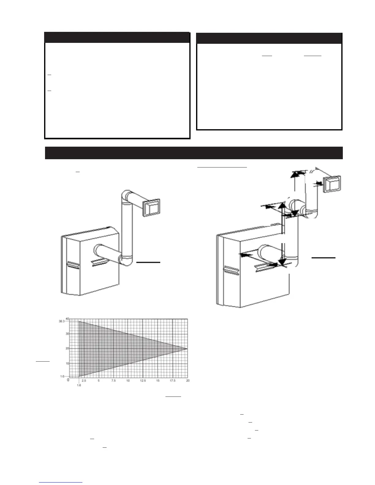
Simple venting configuration (only two 90° elbows)
for the following symbols used in the venting calcula-
tions and examples are:
> - greater than
> - equal to or greater than
< - less than
< - equal to or less than
H
T
- total of both horizontal vent lengths (H
R
) and offsets
(H
O
) in feet
H
R
- combined horizontal vent lengths in feet
H
O
- offset factor: .03(total degrees of offset - 90°
**
**
*) in
feet
V
T
- combined vertical vent lengths in feet
feet inches
1° 0.03 0.5
15° 0.45 6.0
30° 0.9 11.0
45° 1.35 16.0
90°
**
**
* 2.7 32.0
* *
* *
* the first 90° offset has a zero value and is shown in
the formula as -90°
DEFINITIONS
ELBOW VENT LENGTH VALUES
Example 1:Example 1:
Example 1:Example 1:
Example 1:
See graph to determine the required vertical rise V
T
for the
required horizontal run H
T
For vent configurations requiring more than two 90° el-
bows the following formulas apply:
Formula 1: H
T
< V
T
Formula 2: H
T
+ V
T
< 40 feet
REQUIRED
VERTICAL
RISE IN
FEET
V
T
HORIZONTAL VENT RUN PLUS OFFSETS IN FEET
HH
HH
H
TT
TT
T
V
1
=9 ft
V
2
=6 ft
V
T
=
V
1
+
V
2
=
9 + 6 = 15 ft
H
1
=3 ft
H
2
=2 ft
H
3
= 1.5 ft
H
R
= H
1
+ H
2
+ H
3
= 3 + 2 + 1.5 = 6.5 ft
H
O
=.03(four 90° elbows - 90°)
=.03(90 + 90 + 90 + 90 - 90) = 8.1 ft
H
T
=H
R
+ H
O
= 6.5 + 8.1 = 14.6 ft
H
T
+ V
T
=14.6 + 15 = 29.6 ft
Formula 1: H
T
< V
T
14.6 < 15
Formula 2: H
T
+ V
T
< 40 feet
29.6 < 40
Since both formulas are met, this vent configuration is ac-
ceptable.
FIGURE 7
FIGURE 6
H
1
H
2
V
1
V
2
H
3
90°
90°
90°
90°
The shaded area within the lines represents acceptable
values for H
T
and V
T
.
BGD33 & GD33 HORIZONTAL TERMINATION
 Loading...