12
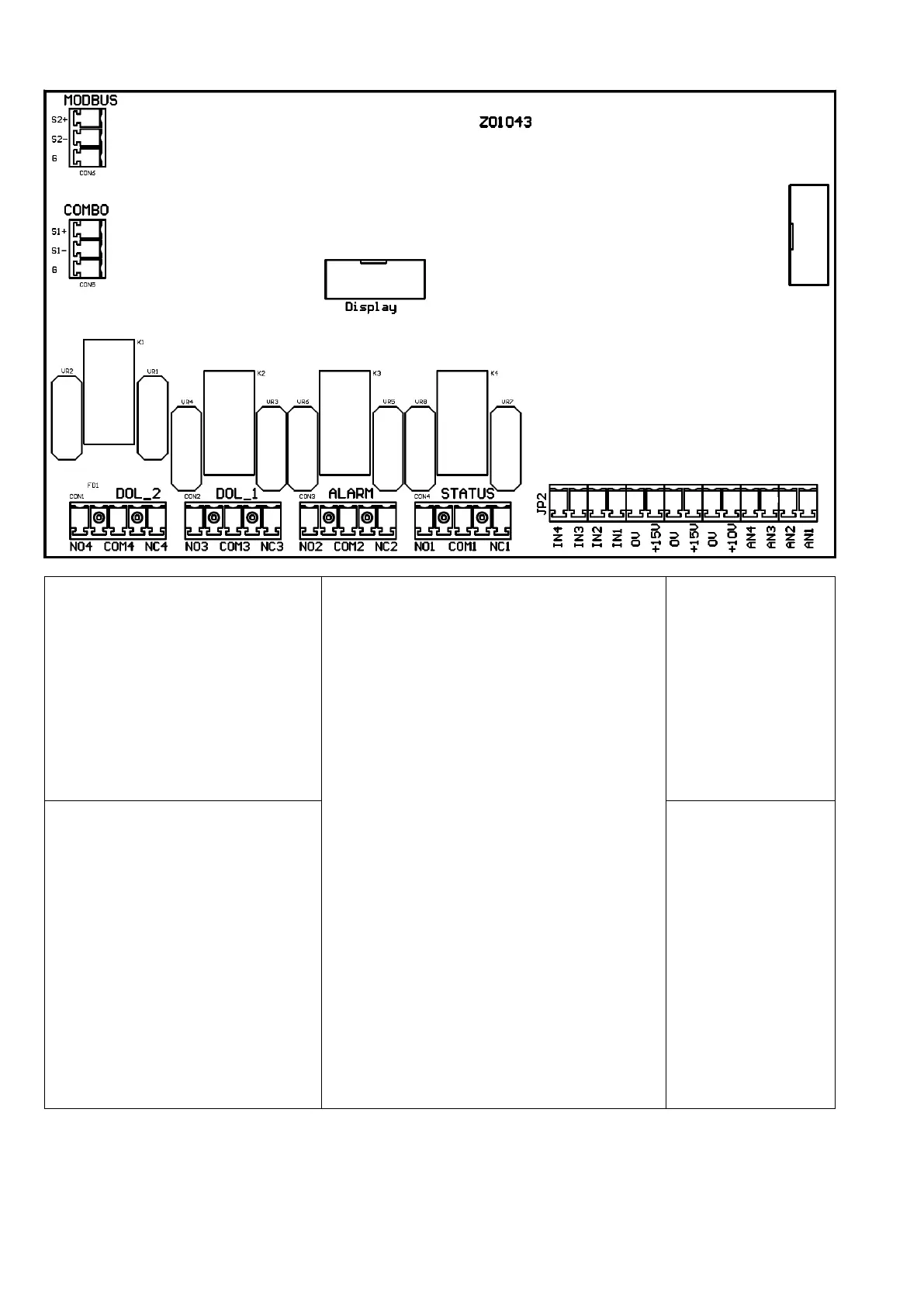
Control board
Analog inputs (10 or 15 Vdc):
1. AN1: 4-20 mA: sensor 1
2. AN2: 4-20 mA: sensor 2
3. AN3: 4-20 mA / 0 - 10 Vdc (settable
by jumper C.C.): external set
4. AN4: 4-20 mA / 0 - 10 Vdc (settable
by C.C.): trimmer for frequency
regulation / external set 2
motor run signal:
NO1, COM1: closed contact with motor running.
NC1,COM1: closed contact with motor stopped.
alarm signal
NO2,COM2: closed contact without alarm.
NC2,COM2: closed contact with alarm or no power
supply.
DOL1 pump relay:
NO3,COM3: closed contact with DOL1 running.
NC3,COM3: opened contact with DOL1 running.
DOL2 pump relay:
NO4,COM4: closed contact with DOL2 running.
NC4,COM4: opened contact with DOL2 running.
Relays are no voltage contacts. Max. voltage to the
contacts is 250 V with max current of 5 A.
S1+
S1-
G
It is recommended to
respect the polarity
linking more units in
series.
Digital inputs:
IN1 : motor start & stop
IN2: value set 1 & 2 switching
IN3: sensor 1 & 2 switching
IN4 : motor start & stop + alarms
reset
0V
We recommend using only no voltage
contacts.
Opening or closing the digital contacts
(depending on software configuration
set (see IN/OUT. parameters) you can
start or stop the motor.
S2+
S2-
G
It is recommended to
respect the polarity.