© National Instruments Corporation 5 BNC-2110 Installation Guide
The BNC-2110 is compatible with all E Series, S Series, and waveform
generation Multifunction DAQ devices. Some of the connectors on this
accessory may have a different function depending on the device to which
it is connected.
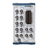
Table 2 describes the BNC connectors on the front panel of the BNC-2110.
Refer to the Connecting Digital/Timing I/O section for terminal block
connector descriptions.
For more detailed information about how the accessory terminals
correspond one-to-one to the Multifunction DAQ device, refer to the I/O
Connector Pinouts Table in the E Series Help at
ni.com/manuals.
Connecting Analog Inputs (E Series and S Series Devices Only)
The BNC-2110 has BNC connectors for up to eight differential analog
input channels. These connectors are labeled AI <0..7>. The number of
connectors you use depends on your DAQ device and your application.
Table 2. BNC-2110 Connector Signal Descriptions
Front Panel BNC Connectors Signal Description
AI <0..1> Differential Analog Input channels 0 and 1
1
AI <2..7>/AO <7..2> Differential Analog Input channels 2 through 7
2
or
Analog Output channels 7 through 2
3
AO <1..0> Analog Output channels 1 and 0
AO EXT REF External reference input connector for analog output
circuitry
PFI 0/AI START TRIG Programmable Function Input 0/Trigger 1—As an input,
one of the PFIs or the source for the hardware analog
trigger; as an output, the AI start trigger
CTR 0 OUT Counter 0 Output—Output terminal from
General-Purpose Counter 0
USER <1..2> User-defined 1 and 2—Connected to USER 1 and USER 2
digital terminal blocks; allow you to use a BNC connector
for a digital or timing I/O signal of your choice
1
E Series devices only, reserved in waveform generation Multifunction DAQ devices
2
When connected to E Series or S Series Multifunction DAQ devices
3
When connected to waveform generation Multifunction DAQ devices
 Loading...