EasyManua.ls Logo

National Instruments BNC-2115 User Manual

National Instruments BNC-2115
12 pages
To Next Page IconTo Next Page
Page #1 background imageLoading...
Page #1 background image
INSTALLATION GUIDE
BNC-2115
Desktop and DIN Rail-Mountable BNC Adapter for E Series Devices
This installation guide describes how to install and configure your
BNC-2115 accessory. If you have not already installed your DAQ device,
refer to the DAQ Quick Start Guide for instructions.
The BNC-2115 is a desktop and DIN rail-mountable BNC adapter you
can connect to data acquisition (DAQ) devices. The BNC-2115 includes
24 BNC connectors and a two-position screw terminal.
The BNC-2115 has one 68-pin connector on the rear panel to connect to
your DAQ device.The 68-pin I/O connector connects to the extended
analog input of 64-channel Multifunction DAQ devices and the extended
digital I/O (DIO) of Multifunction DAQ devices. The BNC-2115 is ideal
for simplifying connections between your measurement apparatus and your
DAQ device in laboratory, test, and production environments.
What You Need to Get Started
To set up and use your BNC-2115 accessory, you need the following:
BNC-2115 BNC adapter
BNC-2115 Installation Guide
SH1006868 cable
One of the following Multifunction DAQ devices:
NI PCI-6033E
NI PCI/PXI-6025E
NI PCI/PXI-6031E
NI PCI/PXI-6071E
NI AT-MIO-64E-3
NI AT-MIO-16DE-10
Question and Answer IconNeed help?

Do you have a question about the National Instruments BNC-2115 and is the answer not in the manual?

National Instruments BNC-2115 Specifications

General IconGeneral
BrandNational Instruments
ModelBNC-2115
CategoryAdapter
LanguageEnglish

Summary

What You Need to Get Started

Installing the BNC-2115

Connecting Signals to the BNC-2115

Connecting Analog Input Signals

Explains using BNC-2115 for analog inputs, recommends differential mode.

Measuring Floating Signal Sources

Details how to measure floating signal sources using the FS switch.

Measuring Ground-Referenced Signals

Describes measuring ground-referenced signals and recommends GS position.

Connecting Analog Output Signals

Recommends GS switch position for analog output signals.

Connecting Digital I/O Signals

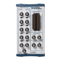
Explains connecting digital signals via BNC connectors and screw terminals.

Operating the BNC-2115 in Single-Ended Mode

How to configure analog input for single-ended modes (RSE/NRSE).

Specifications

Physical Specifications

Details physical dimensions, connectors, and screw terminal plugs.

Environmental Specifications

Specifies operating and storage temperature, and humidity.

Safety Standards

Lists safety standards met by the BNC-2110.

Electromagnetic Compatibility

CE Compliance

Related product manuals