© National Instruments Corporation 11 BNC-2111 Installation Guide
Specifications
This section lists the specifications of the BNC-2111. These specifications
are typical at 25 °C unless otherwise specified.
The PFI / Digital I/O signals are referenced to digital ground from the
connected DAQ board. APFI 0 is referenced to analog output ground from
the connected DAQ board. The PFI signals can be accessed on the center
pin of the applicable BNC connector, while digital ground (analog output
ground for APFI 0) can be accessed on the outer shield of the BNC
connector.
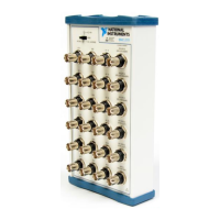
Table 6. BNC-2111 Available Signals
BNC Connector M Series Function E Series Function
AI<0..15> AI<0..15> AI<0..15>
AO<0..1> AO<0..1> AO<0..1>
APFI 0 APFI 0 AO Ext Ref
PFI 0 / P1.0 PFI 0 / P1.0 PFI 0 / AI Start
PFI 2 / P1.2 PFI 2 / P1.2 PFI 2 / AI Convert
PFI 7 / P1.7 PFI 7 / P1.7 PFI 7 / AI Samp
PFI 12 / P2.4 PFI 12 / P2.4 CTR 0 Out
PFI 13 / P2.5 PFI 13 / P2.5 CTR 1 Out

 Loading...