FP-TC-120 and cFP-TC-120 2 ni.com
Installing the FP-TC-120
The FP-TC-120 mounts on a FieldPoint terminal base (FP-TB-x).
Hot plug-and-play enables you to install the FP-TC-120 onto a
powered terminal base without disturbing the operation of other
modules or terminal bases. The FP-TC-120 receives operating
power from the terminal base.
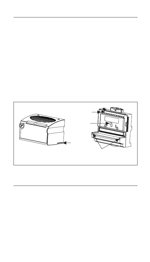
To install the FP-TC-120, refer to Figure 1 and follow these steps:
1. Slide the terminal base key to either position X (for any
module) or position 1 (for the FP-TC-120).
2. Align the FP-TC-120 alignment slots with the guide rails on
the terminal base.
3. Press firmly to seat the FP-TC-120 on the terminal base.
The latch on the terminal base locks the FP-TC-120 into place
when it is firmly seated.
Figure 1. Installing the FP-TC-120
Installing the cFP-TC-120
The cFP-TC-120 mounts on a FieldPoint backplane (cFP-BP-x).
Hot plug-and-play enables you to install the cFP-TC-120 onto a
powered backplane without disturbing the operation of other
modules or connector blocks. The cFP-TC-120 receives operating
power from the backplane.
To install the cFP-TC-120, refer to Figure 2 and follow these steps:
1. Align the captive screws on the cFP-TC-120 with the holes on
the backplane. The alignment keys on the cFP-TC-120 prevent
backward insertion.
Alignment
Slot
Key
Latch
Guide Rails
Terminal BaseI/O Module
 Loading...