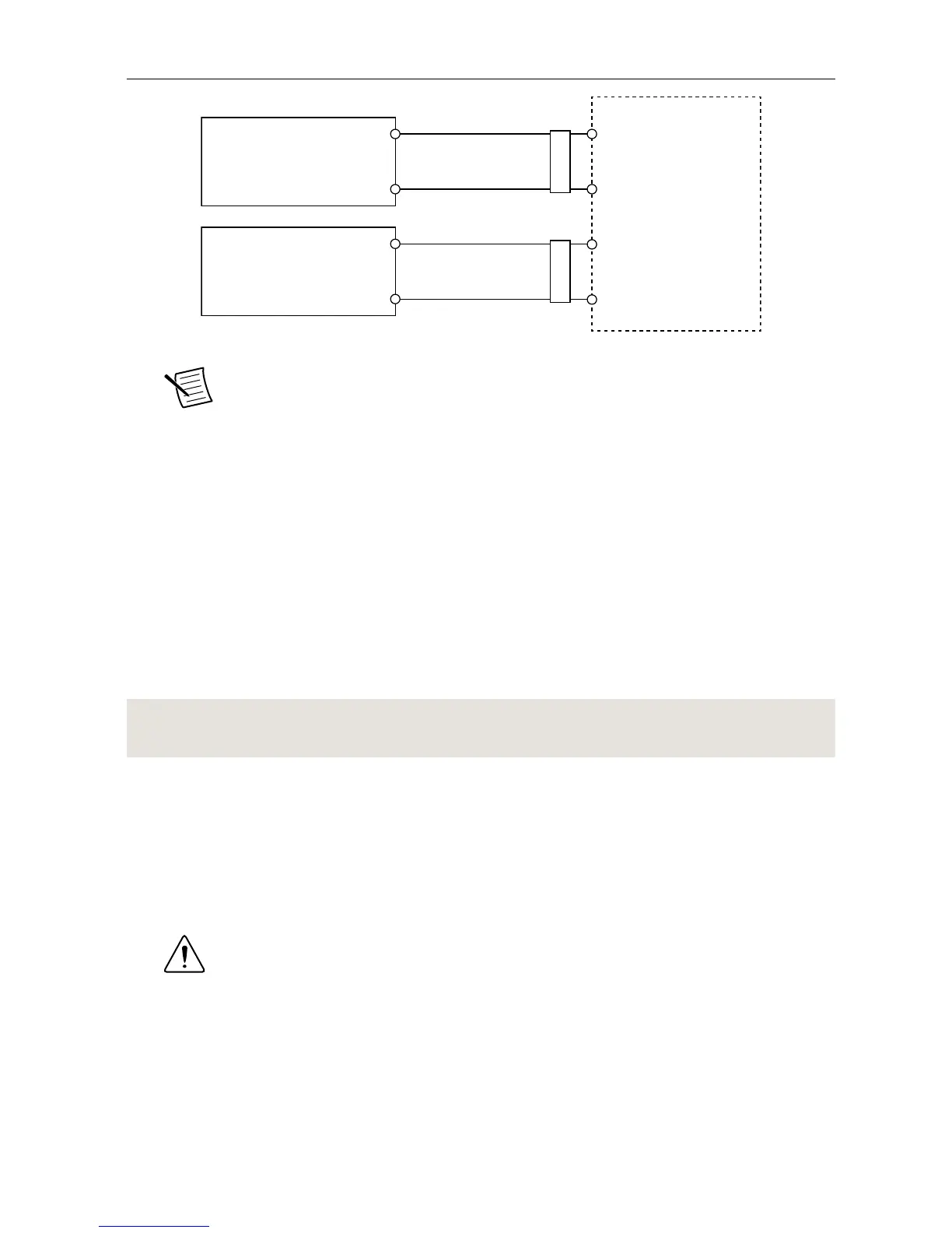
Note The C terminals are internally connected to each other.
5. Tighten the terminal screws on the power connector to 0.20 N · m to 0.25 N · m
(1.8 lb · in. to 2.2 lb · in.) of torque.
6. Install the power connector on the front panel of the cRIO-9039.
7. Tighten the power connector screw flanges to 0.20 N · m to 0.25 N · m (1.8 lb · in. to
2.2 lb · in.) of torque.
8. Power on the primary power supply and optional secondary power supply.
Powering On the cRIO-9039
When you power on the cRIO-9039 for the first time, the device boots into safe mode. The
POWER LED illuminates, the STATUS LED illuminates briefly, and then the STATUS LED
blinks twice every few seconds.
Related Information
STATUS LED Indicators on page 14
Connecting the cRIO-9039 to the Host Computer
Complete the following steps to connect the cRIO-9039 to the host computer using the USB
device port.
1. Power on the host computer.
2. Connect the cRIO-9039 to the host computer using the USB A-to-B cable.
Caution NI requires the use of a locking USB cable (157788-01) to meet the
shock and vibration specifications. Refer to the specifications on ni.com/
manuals for shock and vibration specifications.
10 | ni.com | NI cRIO-9039 Getting Started Guide

 Loading...


