1. Verify that power is not connected to the I/O connector(s) on the C Series module. If the
system is in a nonhazardous location, the cRIO-9039 can be powered on when you install
modules.
2. Press the latches on the C Series module.
3. Align the C Series module with a slot and seat it in the slot until the latches lock in place.
Removing C Series Modules
Verify that power is not connected to the I/O connector(s) on the C Series module before you
remove a module from the cRIO-9039. If the system is in a nonhazardous location, the
cRIO-9039 can be powered on when you remove modules.
Connecting the cRIO-9039
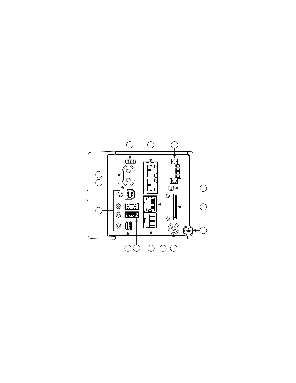
The cRIO-9039 has the following connectors, LEDs, and buttons.
Figure 2. cRIO-9039 Front Panel
1. LEDs
2. Ethernet Ports
3. Power Connector
4. SD LEDs
5. SD Card Removable Storage
6. Ground Screw
7. USER1 Button
8. RS-232 Serial Port
9. RS-485/422 (DTE) Serial Port
10. USB Host Ports
11. Mini DisplayPort
12. Cable Retention Mounts
13. USB Device Port
14. Power and Reset Buttons
Connecting the cRIO-9039 to Ground
You must connect the cRIO-9039 grounding terminal to the grounding electrode system of the
facility.
NI cRIO-9039 Getting Started Guide | © National Instruments | 7

 Loading...


