4-14 | ni.com
Chapter 4 Digital Input/Output and PFI
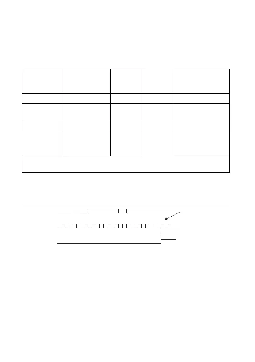
Assume that an input terminal has been low for a long time. The input terminal then changes
from low to high, but glitches several times. When the Filter Clock has sampled the signal high
on N consecutive edges, the low-to-high transition is propagated to the rest of the circuit. The
value of N depends on the filter setting, as shown in Table 4-1.
On power up, the filters are disabled. Figure 4-7 shows an example of a low-to-high transition
on an input that has a custom filter set to N = 5.
Figure 4-7. PFI Filter Example
Table 4-1. Selectable PFI Filter Settings
Filter Setting Filter Clock Jitter
Min Pulse
Width
*
to
Pass
Max Pulse Width
*
to Not Pass
112.5 ns (short) 80 MHz 12.5 ns 112.5 ns 100 ns
6.4 μs
(medium)
80 MHz 12.5 ns 6.4 μs 6.3875 μs
2.56 ms (high) 100 kHz 10 μs 2.56 ms 2.55 ms
Custom User-configurable 1 Filter
Clock
period
T
user
T
user
- (1 Filter Clock
period)
*
Pulse widths are nominal values; the accuracy of the chassis timebase and I/O distortion will affect
these values.
12314123 45
PFI Terminal
Filtered input goes
high when terminal
is sampled high on
five consecutive filter
clocks.
Filter Clock
Filtered Input
 Loading...