NI Digital Waveform Generator/Analyzer Guide 28 ni.com
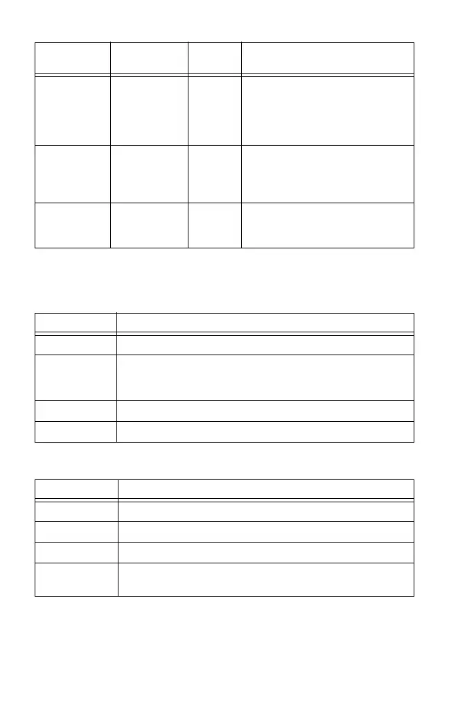
Tables 5 and 6 describe the different conditions indicated by the
two NI PXI LEDs.
Table 4. NI 654x/655x/656x SMB Connectors
Connector
Signal
Name
Signal
Type
Description
CLK IN Reference/
Clock Input
Control Terminal for the external Reference
clock used for the PLL or for the
external Sample clock used for
dynamic generation and/or
acquisition.
PFI 0 Programmable
Function
Interface
(PFI) 0
Control Input terminal to the device for
external triggers, or output terminal
from the device for events.
CLK OUT Reference/
Clock Output
Control Terminal for the exported PLL
Reference clock or the exported
Sample clock.
Table 5. ACTIVE LED Indicators
Color Indications
Off Device not armed, not triggered, or experiencing an error.
Amber Device armed and awaiting Start trigger. If performing a dynamic
acquisition operation, the device may be acquiring pretrigger
samples.
Green Device received Start trigger.
Red Error condition.
Table 6. ACCESS LED Indicators
Color Indications
Off Device not ready.
Amber Device being accessed by software.
Green Device ready to be programmed.
Red Running the niHSDIO Self Test VI or calling
niHSDIO_self_test produced a failure.
 Loading...