© National Instruments | B-35
M Series User Manual
Input Requirements
Refer to the Figure B-41 for the M Series counter/timer circuitry.
Source Period and Pulse Width
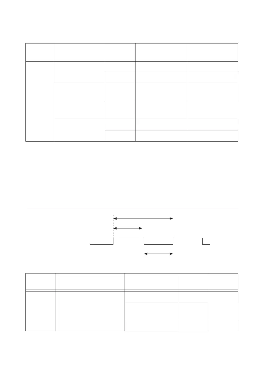
Figure B-46 and Table B-30 show the timing requirements for Counter n Source. The
requirements depend on the synchronization mode.
Figure B-46. Counter n Source Timing Requirements
Table B-29. Selected Gate to Count Enable Delays
Time
Synchronization
Mode
Gating
Mode
Min (ns) Max (ns)
t
4
80 MHz Source Edge 0.5 5.0
Level -1.0 0.5
Other Internal
Source
Edge 1/2 Source Period -
1ns
1/2 Source Period +
3ns
Level 1/2 Source Period -
2.5 ns
1/2 Source Period –
1ns
External Source Edge 7.5 22.0
Level 6.0 18.0
Table B-30. Counter n Source Timing
Time Description
Synchronization
Mode
Min (ns)
*
Max (ns)
t
5
Counter n Source Period 80 MHz Source 12.5 —
Other Internal
Source
25.0 —
External Source 50.0 —

 Loading...


