© National Instruments | B-15
M Series User Manual
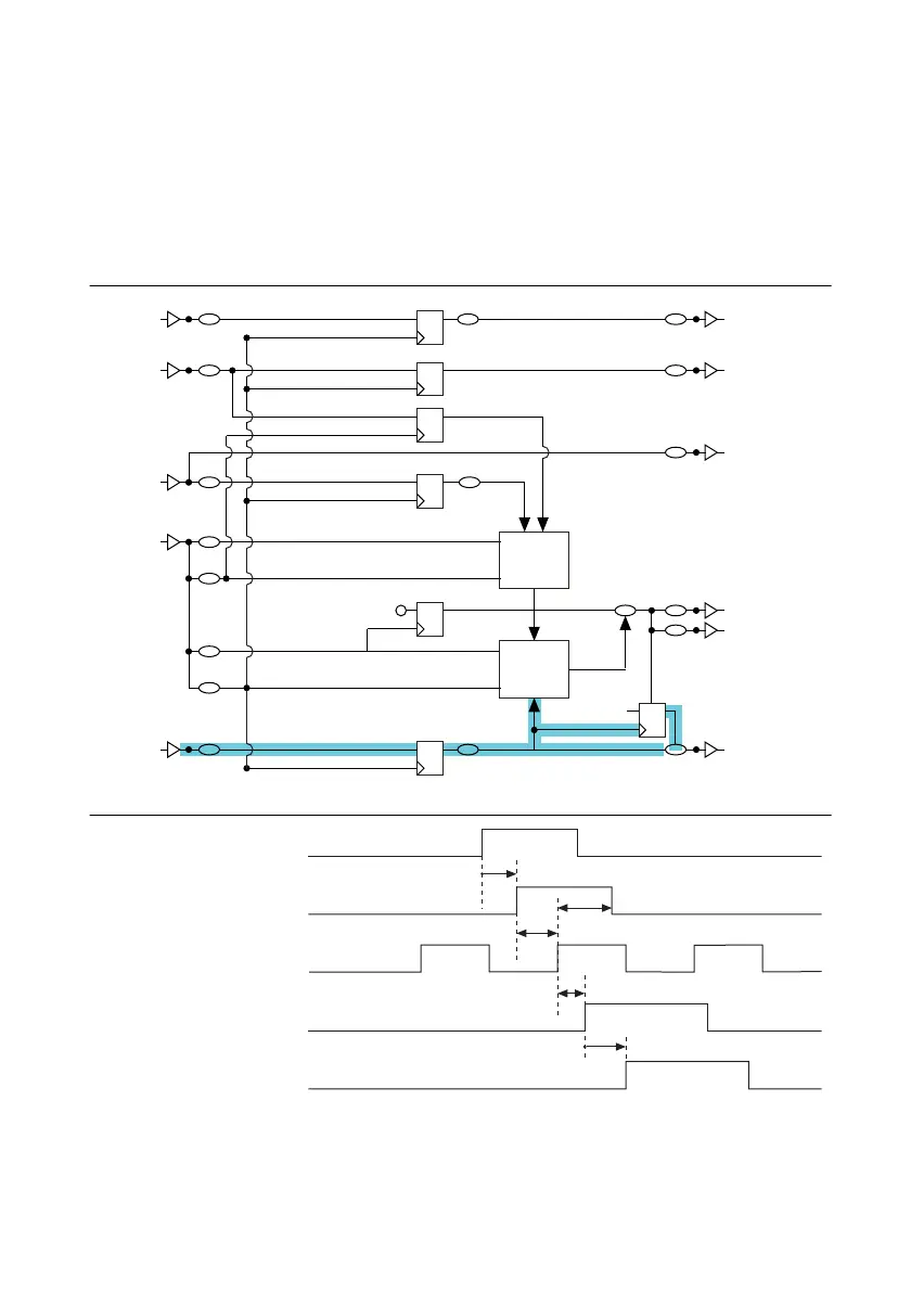
Sample Clock
Sample Clock signals the start of a sample (which, in turn, is a set of converts). Sample Clock is
generated from external or internal sources. The main internal source is the terminal count (TC)
of the SI counter that runs on the Sample Clock Timebase signal. All the sources for Sample
Clock are at the _i level and are selected using a multiplexer. The output of this multiplexer is
called Selected Sample Clock.
Figure B-15. Sample Clock and the Analog Input Timing Engine
Figure B-16. Sample Clock Timing Diagram
SI2_TC
Start Trigger
Terminal
Selected Reference Trigger
Reference Trigger
Terminal
Terminal
Selected Sample Clock
Terminal
Terminal
Terminal
Selected Start Trigger
RTSI
Terminal
Terminal
Terminal
Selected Pause Trigger
SI
Counter
Block
SI_TC
Sample Clock Timebase
Sync Sample Clock Timebase
Convert Clock Timebase
Sync Convert Clock Timebase
SI Start
p_AI_Convert
Start
1
RST
SI2
Counter
Block
Pause Trigger
_i
POUT
Selected Sample Clock
Sync Convert Clock Timebase
Sample Clock
t
27
t
31
t
30
t
29
t
28
 Loading...
