© National Instruments | 4-25
M Series User Manual
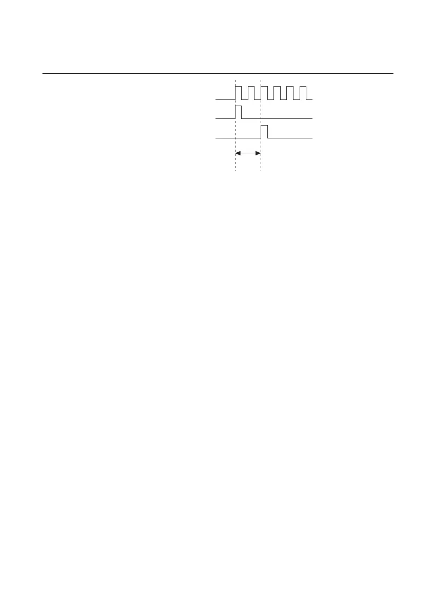
Figure 4-16 shows the relationship of AI Sample Clock to AI Start Trigger.
Figure 4-16. AI Sample Clock and AI Start Trigger
AI Sample Clock Timebase Signal
You can route any of the following signals to be the AI Sample Clock Timebase
(ai/SampleClockTimebase) signal:
• 20 MHz Timebase
• 100 kHz Timebase
• PXI_CLK10
•RTSI <0..7>
• PFI <0..15>
• PXI_STAR
• Analog Comparison Event (an analog trigger)
AI Sample Clock Timebase is not available as an output on the I/O connector. AI Sample Clock
Timebase is divided down to provide one of the possible sources for AI Sample Clock. You can
configure the polarity selection for AI Sample Clock Timebase as either rising or falling edge.
AI Convert Clock Signal
Use the AI Convert Clock (ai/ConvertClock) signal to initiate a single A/D conversion on a
single channel. A sample (controlled by the AI Sample Clock) consists of one or more
conversions.
You can specify either an internal or external signal as the source of AI Convert Clock. You also
can specify whether the measurement sample begins on the rising edge or falling edge of AI
Convert Clock.
AI Sample Clock Timebase
AI Start Trigger
AI Sample Clock
Delay
From
Start
Trigger
 Loading...
