B-26 | ni.com
Appendix B Timing Diagrams
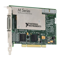
Figure B-31. Start Trigger Path
Figure B-32. Start Trigger Output Delay Timing Diagram
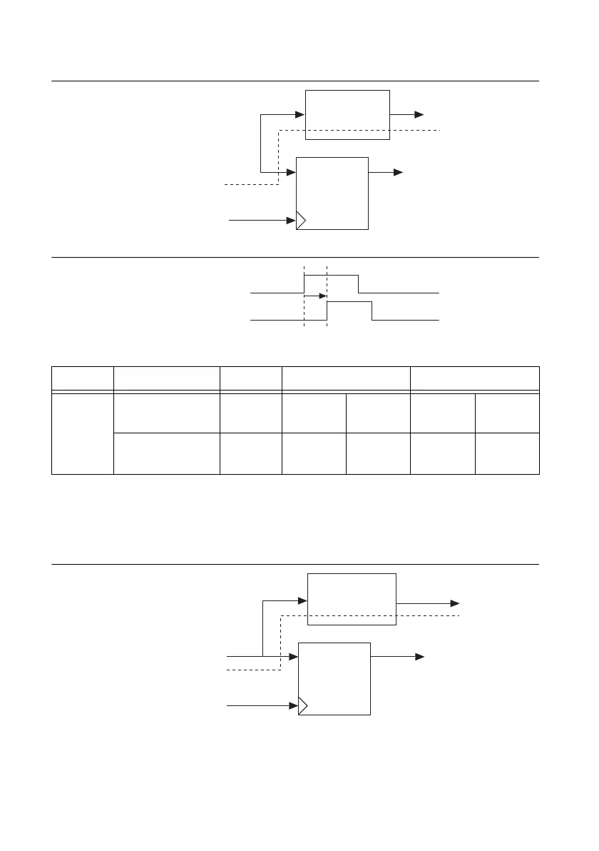
• Pause Trigger—Pause Trigger is only output asynchronously and only to RTSI. The actual
signal being routed is Selected Pause. The Pause Trigger output timing can be derived by
adding the delay in Table B-20 to the total Selected Pause delay.
Figure B-33. Pause Trigger Path
Table B-19. Start Trigger Output Delay Timing
Time From To Min (ns) Max (ns)
t
12
Selected Start
Trigger
PFI 8.1 9.1 27.1 30.8
Selected Start
Trigger
RTSI 7.5 7.7 17.9 18.5
Selected Start Trigger
Sync Sample Clock Timebase
DQ To Internal Logic
Routing Logic
RTSI, PFI
Selected Start Trigger
PFI/RTSI Terminal
t
12
Selected Pause Trigger
Sync Sample Clock Timebase
DQ To Internal Logic
Routing Logic
RTSI
 Loading...
