Chapter 3 Signal Connections
NI 660x User Manual 3-2 ni.com
between two consecutive rising edges of the filter clock timebase. The
frequency of the filter clock timebase determines whether a transition in the
signal may propagate or not. The function of the internal sampling clock is
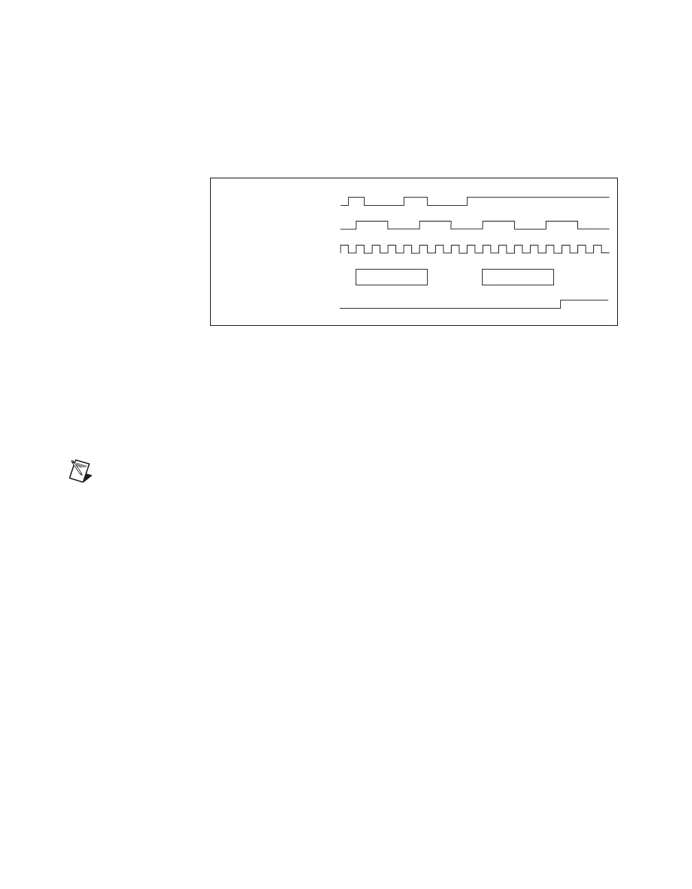
to increase the sampling rate and prevent aliasing. Figure 3-1 demonstrates
the function of this filter.
Figure 3-1. Digital Filtering
In Figure 3-1, the low-to-high transition is guaranteed to be passed through
only if the signal remains high for at least two periods of the filter clock
timebase and is sampled high at each sampling clock rising edge during this
time. Although the low-to-high transition is shown in this example, the
same is true for high-to-low transitions.
Note The effect of filtering is that the signal transition is shifted by two filter clock
timebase periods.
Figure 3-1 shows that if sampling was done at each rising edge of the filter
clock timebase alone, the first two pulses would have been seen as one
continuous transition. However, using the faster sampling clock detects the
glitch; thus, the two short pulses are ignored.
The intent of the filter is to eliminate glitches that may appear on a signal.
The filter is sensitive to the duration for which a digital signal transitions
from one state to another. If a square wave is applied to the filter, its
propagation will depend on its frequency and duty cycle.
There are four filter settings available in the TIO devices: 5 μs, 1 μs, 500 ns,
and 100 ns. The 5 μs filter will pass all pulse widths (high and low) that are
5 μs or longer. It will block all pulse widths that are 2.5 μs (one-half of
5 μs) or shorter. Pulse widths between 2.5 μs and 5 μs may or may not pass,
depending on the phase of the pulse with respect to the filter clock
timebase. The same relationship extends to all other filter clocks.
External Signal
on PFI Line
External Signal Sample
by Maximum Timebase
LHL HH
Filtered PFI Line
Maximum Timebase
Filter Clock
HHH HH
 Loading...